17
Test Procedures
EM90 and EM180 Test Procedures
1. Phase Test
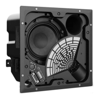
1.1 Remove the grille, procedure 1.
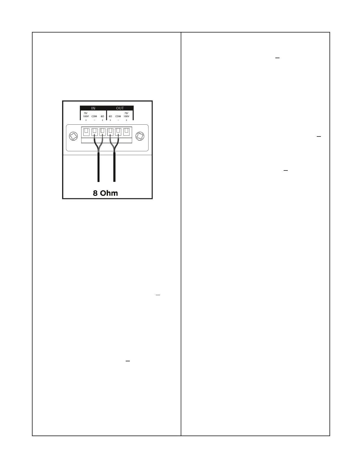
Note: For connection references, refer to the
Male 6 pin diagram posted on this page or
refer to page 8, fi gure 5, 8 Ohm diagram.
1.2 Place one hand on the woofer and gently
touch the dust cap or cone with fi ngers.
Momentarily apply a voltage of 9 Vdc, + 1Vdc
to the 8 ohm input terminal of the 6 pin plug
observing positive and negative polarity.
1.3 Verify the woofer moves outward.
Male, 6 pin plug diagram
3. Rub and Tick Test
3.1 Apply a 10 Hz, 10Vrms, + 1 Vrms signal
to the 8 ohm input.
3.2 Listen carefully for buzzes, rattles or
other extraneous noises from the driver,
woofer or the enclosure.
4. System Sweep with Grille Attached
4.1 Install grille. Apply a 70 Hz, 10 Vrms,
+
1Vrms
signal to the speaker input.
4.2 Change the oscillator frequency slowly
from 70 Hz to 3 KHz, 10 Vrms, + 1 Vrms into
the speaker. Listen carefully for any buzz or
rattle from the grille.
4.3 Replace any defective driver causing a
buzz noise or is defective. There must not
be buzzes, ticks, rubs, bottoming sounds, air
leaks or other unwanted acoustic noises.
2. Air Leak Test
2.1 Apply a 10 Hz, 10 Vrms, + 1 Vrms to the
8 ohm input.
2.2 Slowly increase the input frequency to 70
Hz.
2.3 Listen carefully for air leaks at all gaskets
and joints. Replace any speaker that has a
rubbing or ticking noise.
Equipment Required:
• Audio signal generator
• Male, 6 pin plug, Dinkle, PT: 792047-001S
• Audio amplifi er
 Loading...