15
Disassembly Procedure
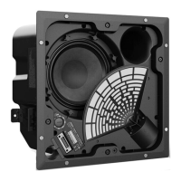
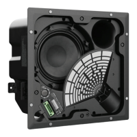
7.6 Remove the one half inch nut to remove
the switch from the baffl e as indicated by the
red arrow, shown in fi gure 29.
7.7 Figure 30, Lift out the switch.
Figure 29
Figure 30
7.8 Figure 31 shows the 6 pin female
connector barrier strip, this is not a
serviceable part. It is sealed to the baffl e to
prevent air leaks.
Note: The 6 pin female connector barrier
strip, is not part of the transformer/rotary
assembly nor is it a serviceable part. When
the transformer/rotary switch assembly is
replaced, there are two wires, white and
pink that must be replaced on the barrier
strip. Technicians should note wire position/
placement before removing from the barrier
strip pins to insure the replacement wires are
reinstalled to the proper pin terminals.
Figure 31
Figure 32
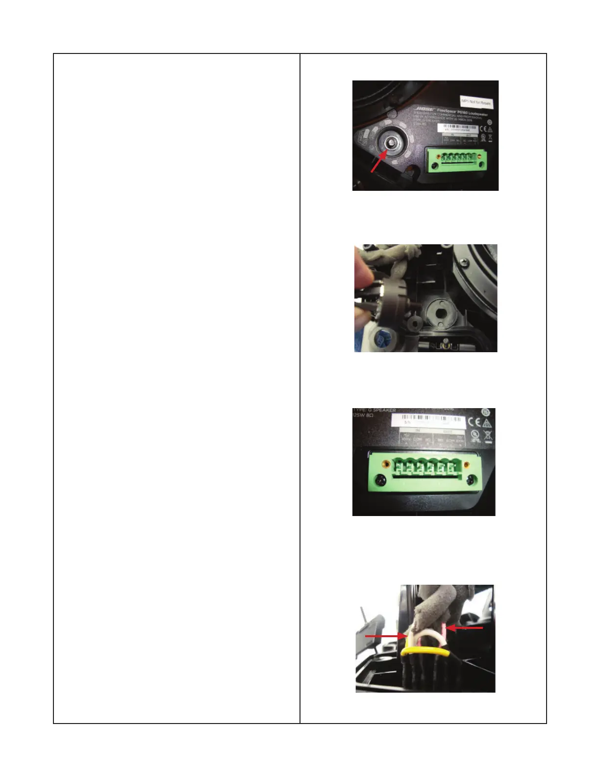
7.9
Figure 32, shows the white and pink
wires that are installed on the barrier strip.
These wires must be removed and replaced
with the replacement harness, transformer
and switch assembly.
 Loading...