EasyManuals Logo

Bose F1 812 Service Manual

Bose F1 812
93 pages
To Next Page IconTo Next Page
To Previous Page IconTo Previous Page
Page #67 background imageLoading...
Page #67 background image
67
DISASSEMBLY PROCEDURES
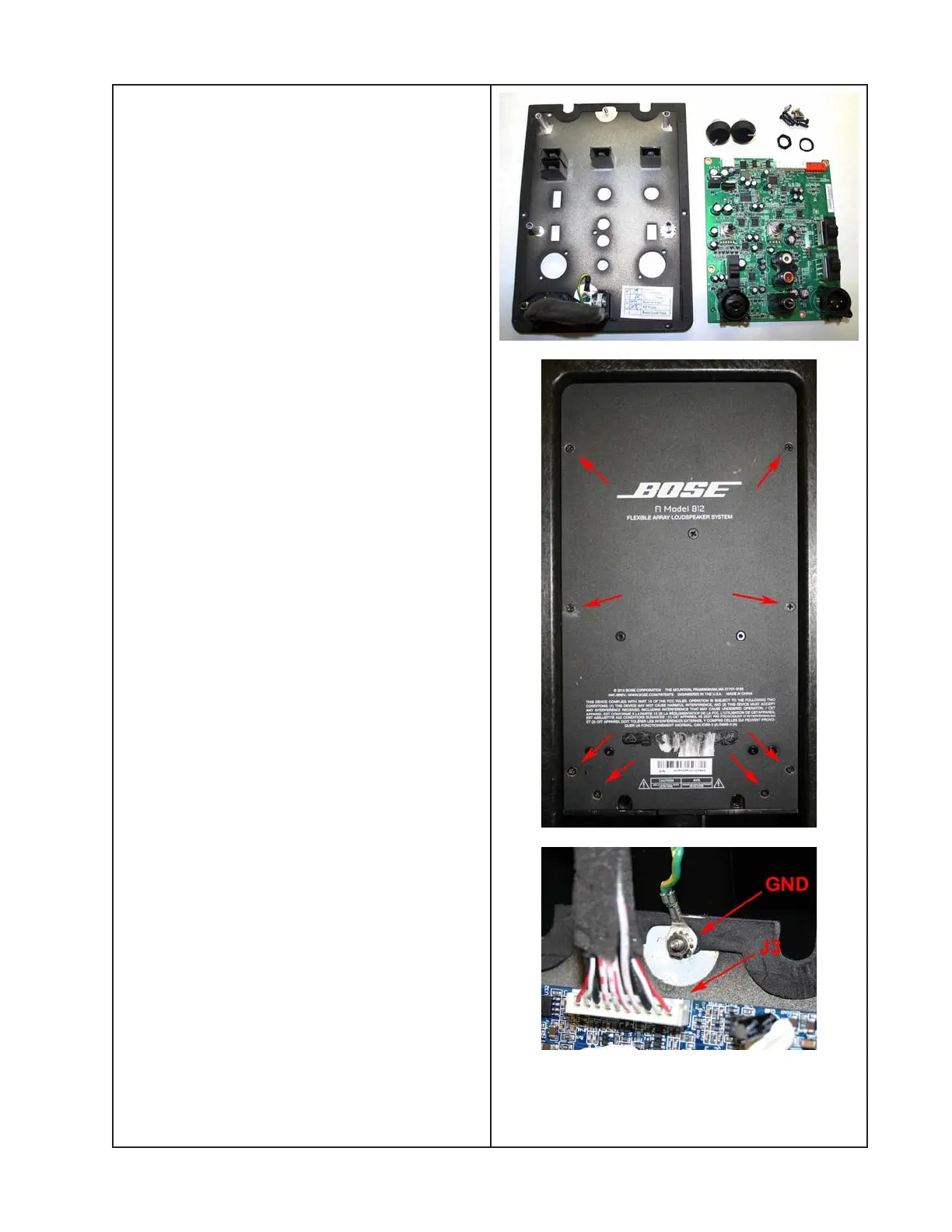
10.3 Disconnect the ground connection wire.
Retain the nut for re-use.
10.4 Disconnect the three wire harnesses at
J1, J2 and J3. Lift off the PCB assembly.
10.5 Remove the two knobs. Remove the
five screws and one nut that secure the
jacks to the panel.
10.6 Turn over the panel and remove the four
screws that secure the PCB assembly to the
panel. Lift off the PCB assembly.
11. SMPS / Amplifier PCB Assembly
Removal
11.1 Remove the eight screws that secure
the SMPS / Amplifier assembly to the loud-
speaker enclosure.
11.2 Carefully lift the SMPS / Amp assembly
away from the enclosure. Take care to not
damage the gasket.

Other manuals for Bose F1 812

Questions and Answers:

Question and Answer IconNeed help?

Do you have a question about the Bose F1 812 and is the answer not in the manual?

Bose F1 812 Specifications

General IconGeneral
TypePowered Speaker
Power Rating1000W
Maximum SPL132 dB
Dimensions664 x 334 x 372 mm
Weight20.2 kg
LF Driver Size12"
Enclosure MaterialComposite
Inputs2 x XLR-1/4" combo
OutputsXLR
Mounting OptionsPole mount
HF Driver Size8 x 2.25" high-output mid-high drivers

Related product manuals