66
DISASSEMBLY PROCEDURES
8.2 Locate the LED PCB on the back of the
front enclosure section. Refer to the photo at
right. Remove the two screws that secure
the PCB to the front enclosure. Lift off the
PCB assembly.
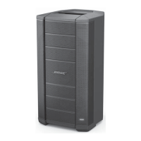
9. Hall Effect Sensor PCB Removal
9.1 Perform steps 7.1 to 7.5 to remove the
front baffle section.
9.2 Locate the Hall Effect Sensor PCB that
you wish to remove on the back of the front
enclosure section. Refer to the photo at the
bottom of the previous page.
Note: There are two Hall Effect Sensor
PCBs, an upper and a lower. Be sure to
remove the correct PCB assembly.
9.3 Remove the one screw that secures the
PCB to the front enclosure. Lift off the PCB
assembly.
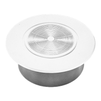
10. DSP / I-O PCB Assembly Removal
10.1 Remove the six screws that secure the
DSP / I-O PCB assembly to the loudspeaker
enclosure.
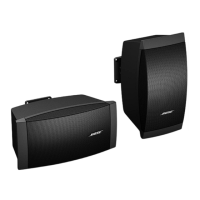
10.2 Carefully lift the DSP / I-O PCB assem-
bly away from the enclosure. Take care to
not damage the gasket.
 Loading...