65
DISASSEMBLY PROCEDURES
Re-assembly Note: The four self-tapping
screws go in the holes at the top of the
enclosure and the eight machine screws are
used along the sides.
7.3 Place the loudspeaker onto its back.
Remove the stand mount interface using
procedure 6.
7.4 Once the screws are removed, you are
ready to separate the woofer baffle from the
loudspeaker enclosure.
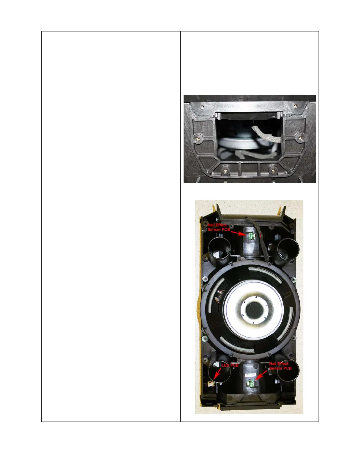
Separate the front section of the enclosure
from the rear section by pulling them apart at
the opening left by the removal of the stand
mount interface. Refer to the photo at right.
Lift off the front enclosure section. Once the
front section has come loose, you can rest
the ports on the internal brackets to allow
disconnecting the wiring harnesses.
Note: Take care to not damage the large
main enclosure gasket. You will need to re-
use it. If you do damage it, you can order a
replacement.
7.5 Disconnect the two Faston connectors
from the woofer. Disconnect the wiring
harnesses at the LED PCB, the two Hall
Effect Sensor PCBs and the Twiddler array
connector. Lift off the front enclosure section.
7.6 Place the front enclosure section face
down on the bench. Remove the eight
screws that secure the woofer to the woofer
baffle. Lift off the woofer.
Notes:
- Be sure to correctly place the main enclo-
sure gasket in the groove along the edge of
the enclosure to ensure there are no air
leaks after the woofer baffle is replaced.
- After woofer baffle replacement, ensure that
there are no air leaks using the test proce-
dures in this service manual.
8. LED PCB Removal
8.1 Perform steps 7.1 to 7.5 to remove the
front baffle section.

 Loading...