69
DISASSEMBLY PROCEDURES
2.2 Pull the bottom edge of the grille away
from the speaker, and slide it down until it
comes out of the groove at the top of the
enclosure. Lift off the grille.
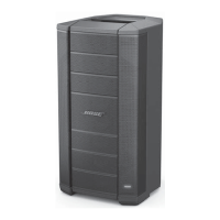
3. LED PCB Removal
3.1 Remove the grille using procedure 2.
3.2 The LED PCB housing is located at the
top right corner of the loudspeaker. Remove
the two screws that secure the LED PCB
housing to the enclosure.
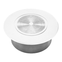
3.3 Disconnect the wiring harness from the
connector. Lift off the LED PCB housing.
3.4 Remove the two screws that secure the
PCB assembly to the housing. Lift out the
PCB assembly.
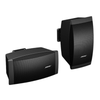
4. Woofer Removal
4.1 Remove the grille using procedure 1.
4.2 Remove the eight screws that secure
the woofer you wish to remove. Lift out the
woofer.
4.3 Disconnect the two Faston connections.
Lift out the woofer.
Note: Be sure to observe polarity when re-
connecting the woofer harness to the new
woofer.
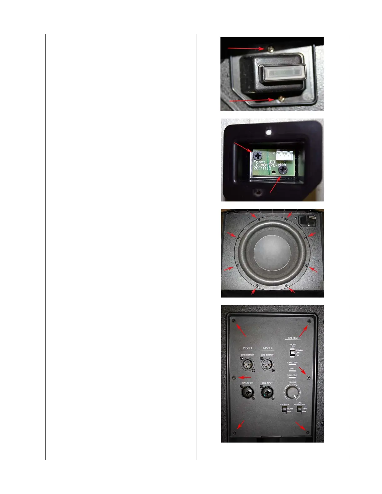
5. DSP / I-O PCB Assembly Removal
5.1 Remove the six screws that secure the
DSP / I-O PCB assembly to the loudspeaker
enclosure. Take care to not strip the screw
heads.

 Loading...