70
DISASSEMBLY PROCEDURES
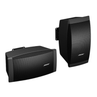
5.2 Carefully lift the DSP / I-O PCB assembly
away from the enclosure. Take care to not
damage the gasket.
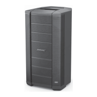
5.3 Disconnect the ground connection wire.
Retain the nut for re-use.
5.4 Disconnect the three wire harnesses at
J1, J2 and J3. Lift off the DSP / I-O PCB
assembly.
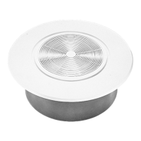
5.5 Remove the knob. Remove the eight
screws that secure the XLR jacks to the
input panel.
5.6 Turn over the DSP PCB subassembly.
Remove the four screws that secure the
PCB assembly to the input panel. Lift off the
PCB assembly.
6. SMPS / Amplifier PCB Assembly
Removal
Important Note: The SMPS / Amplifier PCB
assembly is a densely packed assembly with
many components secured with glue to
prevent vibration and buzzing. Component
level repair is NOT recommended for this
assembly.
 Loading...