8
Product Description
PowerShare
TM
PS602P
The PS602P is a 2-channel portable amplifier that allows its total 600 Watts to be shared asymmetri-
cally across both outputs. Independently control the output level, EQ, and low-impedance/high-imped-
ance (Low-Z/Hi-Z) settings for each output. The PS602P supports built-in loudspeaker EQs for many
Bose
®
Professional loudspeakers as well as a Flat setting. For more customization, use the processing
features in the free web-downloadable PowerShare Editor Software.
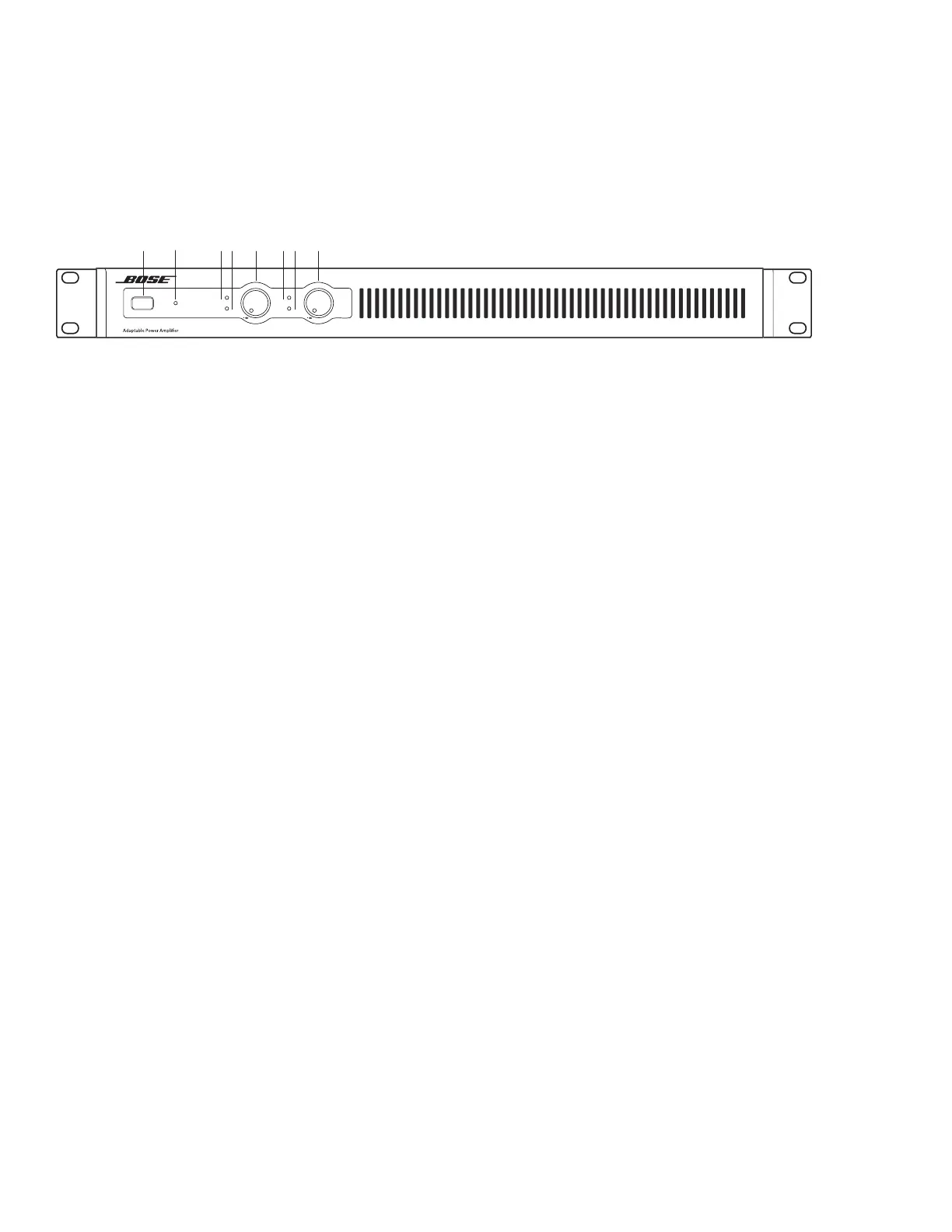
PS602P Front Panel
1. POWER Switch - ON/OFF AC power.
2. POWER LED - Solid green LED indicates the unit is ON. Blinking green LED indicates the unit is in
standby mode. Solid amber LED indicates an over-temperature fault. A solid red LED indicates a power
supply fault.
3 & 6. INPUT 1 & 2 SIGNAL LED - Each LED operates independently.
Relative to each line-level balanced Euroblock input:
• If the SENSITIVITY DIP switch is set to 4 dBu, then the LED is green from -48 dBu to 8.99 dBu,
with a typical input of 4 dBu. LED is amber from 9 dBu to 11.99 dBu. LED goes red, indicating input
clipping, at 12 dBu or over.
• If the SENSITIVITY DIP switch is set to 12 dBu, then the LED is green from -48 dBu to 16.99 dBu,
with a typical input of 12 dBu. LED is amber from 17 dBu to 19.99 dBu. LED goes red, indicating
input clipping, at 20 dBu or over.
Relative to each line-level unbalanced RCA input:
• If the SENSITIVITY DIP switch is set to 4 dBu, then the LED is green from -62 dBV to -6 dBV, with
a typical input of -10 dBV. LED is amber from -5.99 dBV to -3 dBV. LED goes red, indicating input
clipping, at -2.99 dBV or over.
• If the SENSITIVITY DIP switch is set to 12 dBu, the LED is green from -62 dBV to 2.99 dBV, with a
typical input of -2 dBV. LED is amber from 3 dBV to 5.99 dBu. LED goes red, indicating input
clipping, at 6 dBV or over
• Both LEDs will go solid red if a power supply fault is detected.
4 & 7. OUTPUT 1 & 2 LIMIT LED - Each LED operates independently.
• LED is amber when the amplifier is limiting the corresponding output due to exceeding the
specified loudspeaker Vpeak or Vrms limits on an individual channel. If the sum of the amplifier
outputs exceeds 600 Watts peak, then the amplifier will limit all outputs equally, and all LEDs will
show limiting simultaneously. This is because the amplifier is also measuring and limiting total
output power, in addition to individual channel output power. The amplifier is capable of delivering
one-third (1/3) power continuously, 200 Watts peak.
• Each OUTPUT LIMIT LED will go solid red if there is an EHF fault on the corresponding output.
• Both LEDs will go solid red when all outputs are muted due to an amplifier fault, or if there is a
power supply fault.
• Both LEDs will bink red when all outputs are muted from the rear panel mute connector.
5 & 8. OUTPUT 1 & 2 LEVEL Control - Output attenuator for each output. Turn the controls clockwise
to decrease attenuation and counter clockwise to increase attenuation. Fully clockwise is 0 dB attenua-
tion, fully couter-clockwise is mute. The controls are marked in dB of attenuation. There are 21 detents
with the first 12 steps spaced by 1 dB, the next two steps spaced by 2 dB, the following two steps
spaced by 3 dB, and the last two steps spaced by 4 dB, for a total attenuation range of 30 dB prior to
muting. The two most counterclockwise steps are mute.
LIMIT
SIGNAL
1
PowerShare
PS602P
POWER
-2 4
-3 0
-18
-12
-10
-8
-6
-4
-2
0
2
-2 4
-3 0
-18
-12
-10
-8
-6
-4
-2
0
12 345678
 Loading...