English • 11Installation Guide • PowerShare PS604D/PS404D
pro.Bose.com
Product Details
Product Details
PowerShare PS604D/PS404D
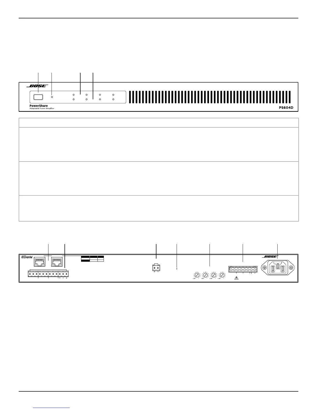
Front Panel
q w e r
POWER
SIGNAL
LIMIT
1234
q Power switch:
On/O AC power.
w Power LED:
Power or fault state indication. Green (solid): Power is on
Green (blinking): Unit is in standby mode
Amber (solid): Thermal fault
Red (solid): Power supply fault
e Input Signal LED:
Each LED operates independently. Green: Signal present
Amber: Input is near clipping
Red (solid): Indicates a fault
Red (blinking): Input is clipping
r Output Limit LED:
Each LED operates independently. Amber: Amplifier limiting an output
Red (solid): Indicates a fault
Red (blinking): Amplifier muted
Rear Panel
Switched* Isolated
Secondary D/C C
Primary D/C D
PRIMARYSECONDARY
INPUT
3
4
21
MUTE
2
0
143
OUTPUT ATTENUATION
OUTPUT
0 0 0
321
PowerShare PS604D
Adaptable Power Amplifier
100-240V ~ 50/60HZ
700W MAX
4
*Connect only one Cat 5 to same network
C = ControlSpace Control
D = Dante Audio
CLASS 2 WIRING
q w e r t y u
q Dante ports: Ethernet ports for connection of Dante® and ControlSpace devices. Transports up to four
digital audio channels between a Dante device and the amplifier. The amplifier supports a THRU path for
daisy-chaining to other Dante devices in switched mode. Dante audio and ControlSpace control can be
separated using Isolated mode.
w Analog Input: Line-level input for balanced analog audio signals.
e Mute port: Normally open or normally closed (consult ControlSpace Designer help system) dry contacts
can mute all outputs.
r Reset button: Resets the amplifier to factory default settings (see Resetting the PS604D/PS404D on page14).
t Output Attenuation controls: Output attenuation controls for each output. Turn the controls clockwise to
decrease attenuation and counter-clockwise to increase attenuation.
y Analog Output: Eight-pin Euroblock connector for loudspeaker connections.
u Power input: Power cord connection (IEC 60320-C14 inlet). Removing the power cord when the amplifier
is on is equivalent to powering down using the front panel power switch, and is an acceptable power-down
method.