EasyManua.ls Logo

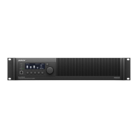
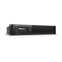
Bose PowerShare PS604D

Bose PowerShare PS604D
24 pages
To Next Page IconTo Next Page
To Previous Page IconTo Previous Page
Loading...
English 23Installation Guide PowerShare PS604D/PS404D
pro.Bose.com
Block Diagrams
Block Diagrams
PowerShare PS604D and PS404D
Output 1
+
9-band PEQ
9-band PEQ
9-band PEQ
9-band PEQ
+
+
+
Sensitivity
Setting:
(4 dBu/12 dBu)
Power
LED
Power
Modes
Auto Standby
Setting:
(O/On)
Output 2
Output 3
Output 4
9-band
Speaker PEQ
9-band
Speaker PEQ
9-band
Speaker PEQ
Band Pass
Band Pass
Band Pass
Band Pass
Mute Connector:
(Open/Short)
+
+
+
+
+
Input 1
Balanced
Input 2
Balanced
Input 3
Balanced
Input 4
Balanced
9-band
Speaker PEQ
Delay
Delay
Matrix Mixer
PWR
AMP
PWR
AMP
PWR
AMP
PWR
AMP
Output Voltage
Setting:
(70V/100V)
C
H
4
C
H
3
C
H
2
Signal LED
CH1
Level
Detect
Level
Detect
Level
Detect
C
H
4
C
H
3
C
H
2
Limit LED
CH1
Digital Signal Processor
O
U
T
4
O
U
T
3
O
U
T
2
Output 1
Setting:
(Hi-Z/Low-Z)
C
H
4
C
H
3
C
H
2
Output Atten
CH1
RJ-45 Connectors
Dante/Control
Secondary
Reset
Button
Primary
OR
Vpk & Vrms
Limiters
Vpk & Vrms
Limiters
Vpk & Vrms
Limiters
Vpk & Vrms
Limiters
OR
OR
OR
Level
Detect
ConÞguration via
ControlSpace Designer Software
Switched/
Isolated
Mode

Related product manuals