1
Instruction Manual
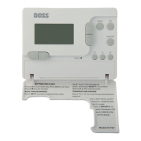
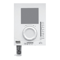
TPSRF51 (957707) - BOSS
TM
Universal RF Programmable Room Thermostat (Wireless)
(7 day, 5/2 day and 24 hour programme options)
Thank you for purchasing this product. If installing for someone else, please ensure that the
instructions are handed to the householder.
Please read this manual prior to installation or use.
Always isolate the mains power supply before removing the unit from the backplate.
Do not mix old and new batteries. Do not use rechargeable batteries.
Please leave these instructions with the end user where they should be kept in a safe place for
future reference
Installation
TPSRF51 Control Unit is easily installed using the backplate supplied with the unit – this is purely
for mounting purposes, as no wiring is needed for the Control Unit. The backplate can be mounted
directly to the wall surface without using a back box.
The ideal position to locate the TPSRF51 RF Programmable Room Thermostat is about 1.5m above
floor level, in a location where the thermostat is accessible, reasonably lit and free from extremes
of temperature and draughts. Do not mount the thermostat on an outside wall, above a radiator or
in a location where it may be subjected to direct sunlight.
To ensure trouble free receiving of the Radio Frequency (RF) signal, always ensure that the
programmable thermostat is mounted away from any possible sources of interference (such
as radio, TV sets, computer, etc.), locating the TPSRF51 in enclosed areas such as cellars and
basements is not recommended, position your thermostat where the temperature will be
representative of that in the zone being controlled.
Connecting the TPSRF51 RF Receiver
NOTE : All electrical installation work should be carried out by a suitably qualified Electrician or other
competent person.
If you are not sure how to install this digital thermostat consult either with a qualified electrician,
heating engineer or your boiler/heating system supplier for advice on how to continue.
The TPSRF51 Receiver should be mounted in a suitable location that is both accessible for the
connection of mains and control wiring, and allows good reception of the RF signal. The Receiver
needs a 230V AC mains supply to operate, and this should be fused appropriately (13A max.) The
Receiver should be mounted in a location where it will not come into contact with water, moisture
or condensation.
The Receiver On/Off switch is accessible from the front face of the Receiver.