3
Control Unit Jumper Settings
Changes to the jumper settings should only be made by the Engineer carrying out the installation
or other qualified person.
The installer should select the jumper positions required if changes need to be made to the
factory default settings. These jumpers are found on the rear of the Control Unit.
Jumpers Description
Address code
5 DIP switch levers for 5 bits address code for RF communication
(All jumpers default are closed)
Span
3x1 pins jumper for +/-0.5°C or 1.0°C (factory default setting) selection
It is used to define the system to run at +/-0.5°C or 1.0°C difference to the
set temperature
Notes :
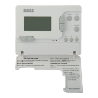
The Reset button must be pressed after changing jumper positions.
The Reset button is accessible behind the small hinged door on the front right hand side of the Control Unit.
RF Address Code Setting
If there is another unit being used nearby, e.g. in the next house or as part of a multiple
installation, your Receiver may be triggered by the other Control Unit. You can change the
RF Address Code to help to prevent this problem.
Each Receiver can only respond to RF transmissions from a Control Unit that has the same
RF address code setting.
Disconnect any AC power to the Receiver, and remove the batteries from the Control Unit before
attempting any adjustment of the RF Address Code switch and jumpers. If you are not sure how
to carry out this operation correctly, consult either with a qualified electrician or heating engineer.
To adjust the RF address code of the Receiver, simply push up one or more of the 5 DIP switch
levers on the DIP switch bank located on the back of the Receiver, and then make a note of the
setting of each switch.
To adjust the RF address code of the Receiver, simply push up one or more of the 5 DIP switch
levers on the DIP switch bank located on the back of the Receiver, and then make a note of the
setting of each switch. Then set the 5 DIP switch levers on Control Unit same as the RF Receiver
setting so that the address code settings match each other.
For example, if Receiver DIP switches set as following,
Controller unit dip switch should be set as same:
You must press Reset on the Control Unit after making any changes to the RF address
code settings.
Testing the RF Transmission
It is important to site both the Receiver and Control Unit in locations where the RF signal cannot
be interrupted.
1 – ON
2 - OFF
3 - OFF
4 - OFF
5 - ON