2
On the front cover of the Receiver you will see that there is the On/Off switch and two light
emitting diodes (LEDs). The switch allows you to turn off the Receiver if necessary to prevent
it calling for heat. The top LED (orange) will illuminate when the switch is in the “On” position
and the unit is receiving power. The bottom LED (green) illuminates when the Receiver unit is
receiving a heat call transmission from the Control Unit.
The wiring terminals and RF Address Code setting DIP switches are located on the rear of the
Receiver.
Receiver Wiring Terminals
Terminal Name Function
N Neutral input 230VAC/50Hz
L Live input 230VAC/50Hz
1:COM Switch common terminal
2:NO Normal open (Volt-Free Contact)
3:NC Normal close (Volt-Free Contact)
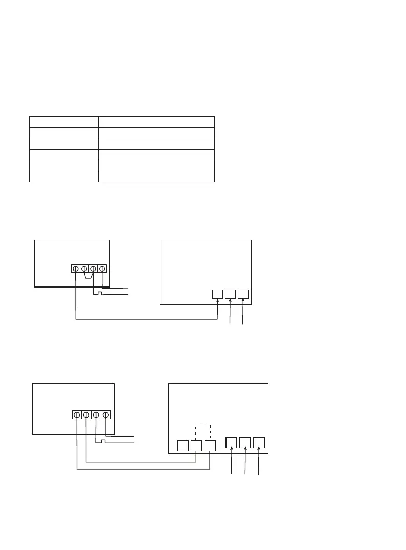
Direct Control Boiler
RECEIVER
N.0. COM L N
N
L
BOILER
Live Feed
N E
L N E
MAINS
FEED
Brown
Green/Yellow
Blue
Brown
Blue
Notes: Receiver unit should have a permanent 230V AC main supply
Combi Boiler
RECEIVER
N.0. COM L N
N
L
BOILER
Live Feed
L N E
MAINS
FEED
N L SL
Thermostat (Remove link)
Brown
Brown
Brown
Brown
Blue
Notes:
• Receiver unit should have a permanent 230V AC main supply
• If the boiler has two terminals for the thermostat, remove the link from the boiler