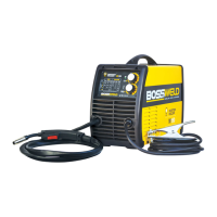
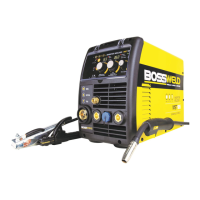
The BOSSWELD M150 Inverter DC MIG Welder is a portable welding machine designed for both Gas and Gasless MIG welding, suitable for home, DIY workshop, and rural applications. It utilizes IGBT Inverter welder technology to provide smooth welds.
Function Description:
The M150 is an inverter MIG welder that feeds MIG wire through a gun to create a weld pool. It can operate with or without shielding gas, where gas or flux prevents oxidation in the weld. Users simply point the gun and pull the trigger to weld. It is ideal for maintenance, small projects, and automotive repairs. The welder can be used with mild steel, stainless steel, and aluminum.
Important Technical Specifications:
- Model: M150 Inverter MIG Welder
- Input Voltage: 240V AC (15 Amp input plug required)
- Open Circuit Voltage (Uo): 53V
- Duty Cycle (X):
- 15% at 150A / 21.5V
- 60% at 78A / 17.8V
- 100% at 60A / 17V
- Input Current (I1max): 30A
- Effective Input Current (I1eff): 12A
- Weight: 9Kg
- Protection Class: IP21
- Standard: IEC 60974
- Warranty: 2-year limited warranty
Usage Features:
- Front Panel Controls:
- Wire Speed / Voltage Table: Provides guidance for setting wire speed and voltage based on wire size and material thickness.
- Power Indicator Light: Indicates when the machine is powered on.
- Overload Error Indicator: Illuminates if the welder enters "thermal overload" to protect the unit and user.
- Welding Speed Adjustment: Knob to control wire feed speed.
- Welding Voltage Control Knob: Knob to adjust welding voltage.
- MIG Torch: Direct connect 15 Series MIG Torch.
- Welding Earth Lead: Direct connect earth lead.
- Rear Panel Features:
- Mains Power Switch: On/Off switch for the machine.
- Gas Input: Connection for shielding gas hose.
- 240V AC Mains Power Cord with 15 Amp Input Plug.
- Cooling Fan: For thermal management.
- Side Panel (Wire Feed Unit):
- Spool Hub and Nut: For mounting wire spools.
- Drive Roller Cover: Protects the drive roller.
- Drive Roller: Feeds the welding wire. Different groove types (V-groove for mild steel, U-groove for aluminum, V-knurled for gasless wire) are available and must match the wire type and size.
- Guide Tube and Inlet Tube: Guide the wire from the spool to the torch liner.
- Wire Feed Tensioning Knob and Arm: Adjust tension on the wire to ensure smooth feeding.
- Idle Roller: Assists in wire feeding.
- Wire Feed Inching: Button to manually feed wire.
- Polarity Switching Terminal: Allows switching between DCEN (Gasless) and DCEP (Gas) welding.
- Polarity Settings:
- DCEN (Direct Current Electrode Negative) for Gasless Welding: The torch is connected to the negative terminal, and the earth clamp to the positive terminal.
- DCEP (Direct Current Electrode Positive) for Gas Welding: The torch is connected to the positive terminal, and the earth clamp to the negative terminal.
- Wire Spool Setup:
- Open the side door, remove the spool hub nut, and place the wire spool on the hub.
- Ensure the wire rolls from under the spool into the wire feeder.
- Replace the spool hub nut and adjust firmly without overtightening.
- Release the wire feed tensioning knob, feed the wire into the guide tube and inlet tube (approx. 3-5cm into the torch liner).
- Put down the wire tensioning arm and gently tighten the tensioning knob.
- MIG Torch Setup:
- Remove the nozzle and contact tip from the torch.
- Plug the machine into a 240V outlet and switch it ON.
- Press the wire feed button (inside the machine door) to push the wire through the torch. Ensure the torch is straight with no kinks.
- Reinstall the contact tip over the wire and tighten (do not overtighten).
- Reattach the nozzle to the torch.
- Trim the wire to the end of the nozzle.
- Gas MIG Welding Setup:
- Connect the earth clamp to the workpiece, ensuring good contact with bare metal.
- Fit the gas regulator to the gas bottle and install the gas hose to the gas inlet on the rear panel.
- Turn on the regulator and set gas flow to 10-15 L/min.
- Refer to the chart on the front panel for voltage and wire speed settings.
- Gasless MIG Welding Setup:
- Follow the same steps as Gas MIG welding for earth clamp connection and machine power-up.
- No gas bottle or regulator is required.
- Ensure the correct knurled drive roller for gasless wire is installed.
- Set polarity to DCEN.
- Welding Guides:
- MIG Gun Position: Angle of the MIG gun (push, perpendicular, drag) affects weld run width.
- Distance from Nozzle to Workpiece: 2.0-5.0mm for gas shielded wire, 5.0-10.0mm for gasless wire.
- Travel Speed: Influences weld width and penetration. Faster speed for thin steel, slower for thick steel.
- Wire Size Selection: Depends on metal thickness, joint configuration, wire feed unit capacity, penetration, deposition rate, bead profile, welding position, and cost.
- Shielding Gas Selection: Chart provided for Mild Steel (Argon/Co2 - Co2), Stainless Steel (Argon/o2 - Argon/Co2), and Aluminium (Argon).
- Test Welds: Advised to run a few test welds on scrap material to tune settings before the actual job.
Maintenance Features:
- General Care: Wipe the welder down with a clean, soft, dry cloth after use.
- Cable Inspection: Regularly inspect welding cables, earth clamp, and electrode holder for damage.
- Torch Consumables: Frequently inspect and replace MIG gun front-end consumables (nozzle, contact tip, gas diffuser) due to heat and spatter exposure. Use MIG pliers to clean spatter.
- Wire Feed Unit: Ensure the drive roller matches the wire size and type.
- Gas Leak Check: At initial setup and regularly, check for gas leaks by applying soapy water to connections and clamps; bubbles indicate a leak.
- Storage: Store the welder and accessories in a dry place, out of children's reach, preferably in original packaging, secured against falling or rolling.
- Troubleshooting Guide: Comprehensive chart for common issues like power indicator not lit, no output current, unstable output, hot clamp, excessive spatter, porosity, wire stubbing, lack of fusion, excessive/lack of penetration, and no gas flow, with possible reasons and suggested remedies.
- MIG Wire Feed Troubleshooting: Specific guide for inconsistent/interrupted wire feed issues, including wrong dial adjustment, incorrect polarity, incorrect speed/voltage, long/kinked torch lead, worn/clogged liner, misaligned wire, incorrect/worn drive roller, too much tension, tangled/contaminated wire.
- Recommended Products for Maintenance:
- Bossweld Aerosol Anti Spatter Spray (Part No: 800041): Silicon-free coating to prevent spatter from sticking.
- Bossweld Tip Dip Gel (Part No: 800055): Non-toxic, water-based gel to prolong nozzle and tip life.
- Bossweld 8 Ways MIG Welding Pliers (Part No: 800074): Multi-function pliers for nozzle/tip removal, cleaning, and wire cutting.
- Personal Protective Equipment (PPE): Always use protective gloves, fire-resistant clothing, and a welding helmet. Safety glasses are needed for brushing, chipping, or grinding.
- Work Area Safety: Ensure a clear, well-lit, well-ventilated work area, free from flammable materials. Maintain easy access to the ON/OFF switch and electrical mains. Do not expose the welder to rain or damp conditions.
- Electrical Contact: Use adequate electrical insulation. Avoid direct contact with the welding circuit. Use an RCD (Residual Current Device) for additional protection. Avoid extension leads; if used, ensure they are suitable current rating, heavy-duty, earthed, and kept away from moisture/heat.
- Fumes & Gases: Welding produces harmful fumes and gases. Work in a well-ventilated area, use fume extraction, or wear an approved air-supplied respirator in confined spaces. Do not weld near degreasing, cleaning, or spraying operations. Avoid welding materials that produce toxic fumes (galvanized, lead, cadmium plated steel) without proper ventilation/respirator.
- Fire Risk: Welding produces sparks and molten metal. Keep the area clear of inflammable materials and have a fire extinguisher/welding blanket on hand.
- Workpiece: Remains hot for a long time; use welding gloves, pliers, or tongs.
- Switching Off: Always switch off the welder and disconnect from mains when finished or unattended.
- Improper Use: Do not use the welder for purposes other than intended (e.g., thawing pipes).
- Handling: Use safe lifting practices. Position the machine on a horizontal surface capable of supporting its weight.
- Internal Maintenance: No user-serviceable parts inside. Refer to qualified service personnel for internal maintenance.
- Plug Modification: Do not grind the plug, as this will void the warranty.
- Duty Cycle Overload: If the duty cycle is exceeded, the welder will automatically stop output and the thermal overload light will illuminate. Allow the machine to cool down before resuming. Exceeding the duty cycle is not grounds for warranty.