ENGLISH
6
Fig. G
6
3
Actuating Tool (Fig. A)
WARNING: To reduce the risk of injury, ALWAYS
wear proper eye ANSI Z87.1 (CAN/CSA Z94.3) and
hearing protection ANSI S12.6 (S3.19) when operating
thistool.
WARNING: Keep fingers AWAY from the trigger when
not driving fasteners to avoid accidental actuation.
Never carry a tool with finger on the trigger. The tool
will drive a fastener if the contact trip is bumped
while the trigger isdepressed. Serious injury could
result if the trip accidentally contacted someone or
something, causing the tool tocycle.
Contact Actuation Trigger - (Fig. A)
The contact trigger
1
is intended for rapid fastening on flat,
stationarysurfaces.
Using the contact trigger, two methods are available: place
actuation and contactactuation.
To Operate the Tool Using the PLACE ACTUATION
Method
1. Depress the contact trip
4
against the worksurface.
2. Pull the trigger to drive thefastener.
3. Allow the tool to recoil off the work surface
To Operate the Tool Using the CONTACT ACTUATION
Method
1. Pull thetrigger.
2. Depress the contact trip
4
against the work surface. As
long as the trigger is pulled, the tool will drive a fastener
every time the contact trip is depressed. This allows the
user to rapidly drive multiple fastener insequence.
Single Sequential Trigger -
WARNING: Allow the tool to recoil off the work
surface after actuation. If the contact trip remains
depressed, a nail will be driven each time the trigger is
released and pulled, which could result in accidental
actuation, possibly causinginjury.
The sequential actuation trigger’s intended use is for
intermittent fastening where accurate fastener placement
isdesired.
To operate the tool in single sequential
actuationmode
1. Depress the contact trip
4
firmly against the
worksurface.
2. Pull thetrigger.
3. Allow the tool to recoil from the worksurface.
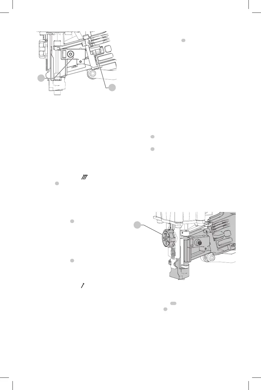
Adjusting Depth (Fig. H)
WARNING: To reduce risk of serious injury from
accidental actuation when attempting to adjust
depth, ALWAYS:
• Disconnect air supply.
• Avoid contact with trigger duringadjustments.
The depth that the fastener is driven can be adjusted using
the depth adjustment next to the trigger of the tool. The
depth of drive is factory adjusted to a nominal setting. Test
drive a fastener and check depth. If a change is desired:
1. To drive the nail shallower, rotate the depth adjustment
wheel
5
to theright.
2. To drive a nail deeper, rotate the depth adjustment
wheel
5
to theleft.
The adjustment wheel has detents every 1/4 turn. Test drive
another fastener and check depth. Repeat as necessary to
achieve desired results. The amount of air pressure
required will vary depending on the size of the fastener
and the material being fastened. Experiment with the air
pressure setting to determine the lowest setting that will
consistently perform the job at hand. Air pressure in excess
of that required can cause premature wear and/or damage
to thetool.
Fig. H
5
Shingle Guide (Fig. I, J)
Adjust Shingle Guide
1. Loosen the screw
13
with a hex wrench and slide the
shingle guide
7
to the desiredposition.
2. Retighten the screw with firmly.