06 07
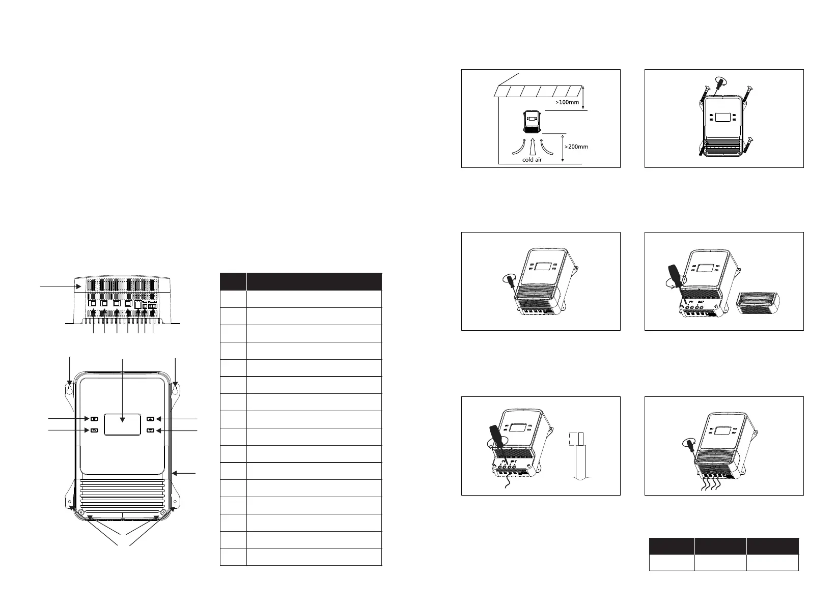
6. Mounting Instruction
Step 3: Remove the End Cover
The screws are hidden design, so the end cover needs to be
removed for wiring. Use a cross or flathead screwdriver to
loosen the screws counterclockwise. There are two screws
in total. After removing them, set them aside. Once the
wires are connected, the end cover should be reinstalled.
Step 4: Loosen the Screws
Place the end cover aside and use a flat or cross-head
screwdriver to unscrew all the wiring screws in a
counterclockwise direction until there is resistance.
Step 1: Site Selection
The installation environment should be dry and well-
ventilated. It is best to have no obstructions in all directions,
as shown in the figure. The product has a high power
output, which generates a large amount of heat, so please
reserve enough space for heat dissipation.
Step 2: Fixed
Due to the external design, the installation method is
relatively flexible, and users can choose self-tapping screws
or other screws. Firm installation is required to prevent
loosening.
Step 5: Wiring
Prepare the wiring, including the PV positive and negative,
battery positive and negative, optional communication,
temperature control or parallel connection. Strip the
corresponding wires and insert them into the appropriate
ports. Tighten the screws clockwise in sequence. It is
recommended to install circuit breakers for both PV and
batteries.
Step 6: Replace the End Cover
Reinstall the screws that were removed in a clockwise
direction.
8m m
100A 125A
Current
Air Circuit
Breaker
80A 100A
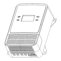
5. Product Appearance
· Industrial grade design: it can be used in various harsh environments. Over-temperature
protection: when the controller is over-temperature, the system will automatically reduce
the charging power. If the external environment is over-temperature, the charging will be
turned off.
· Over-temperature protection: when the controller is over-temperature, the system will
automatically reduce the charging power. If the external environment is over-
temperature, the charging will be turned off.
· More comprehensive electronic protection function: battery and solar panel reverse
connection protection, over-voltage protection, PV over-voltage protection, etc.
· Support mobile APP monitoring, you can check and modify the controller information
(users can download the APP through the IOS or Android system application store).
1
2
3
4
5
6
7
8
9
10
11
12
13
Minus
LCD Screen
PV Negative Pole
PV Positive Pole
BAT Negative Pole
BAT Positive Pole
RS485 Communication Port
External Temperature Port
Parallel Wired Port
End Cover
End Cover Installation Hole
Installation Hole
5
1 3
16
14
15
1515
Description
#
6
7 8
9
10
1112
13
14
15
16
Grounded
Setting
Return
Plus
2
4