4 Preparation
24 ARC PLUS Operating Manual 900-001_IFU_V1.0_11270-S0-20130118-EN
Secure the argon gas bottle with the plastic strap provided for this purpose.
Always place the ARC PLUS device below the HF device.
The equipment trolley must be positioned outside the operating theatre zone
with a potential risk of explosion.
Ensure free circulation around the devices. Maintain a room temperature
between +10 °C and + 40 °C and a relative humidity between 0 and 75%.
To achieve the full dispensing accuracy of the ARC PLUS device, the device
should be switched on approximately 10 minutes before the start of surgery.
The ARC PLUS coagulation unit may alternatively be connected to a central
argon supply system. Along with the device configuration, the argon gas
purity grade specified by BOWA and the specifications for the maximum inlet
pressure must be met. The responsibility for meeting these specifications
rests with the hospital maintenance department.
Connect the HF device and the ARC PLUS device to the equipotential rail
with separate cables.
Use the provided Y extension power cable or a mains power cable of equal
quality with the appropriate national mark of approval.
Connect the power cable of the HF device to the supplied Y extension power
cable and connect it to the HF device and the ARC PLUS, and connect to the
power cable to the AC mains.
NOTE
Verify that the actual AC mains voltage matches the rated voltage range
specified for the device.
Connect the two fibre optic cables to the corresponding connectors 6 and 7 of
the ARC PLUS and the HF device.
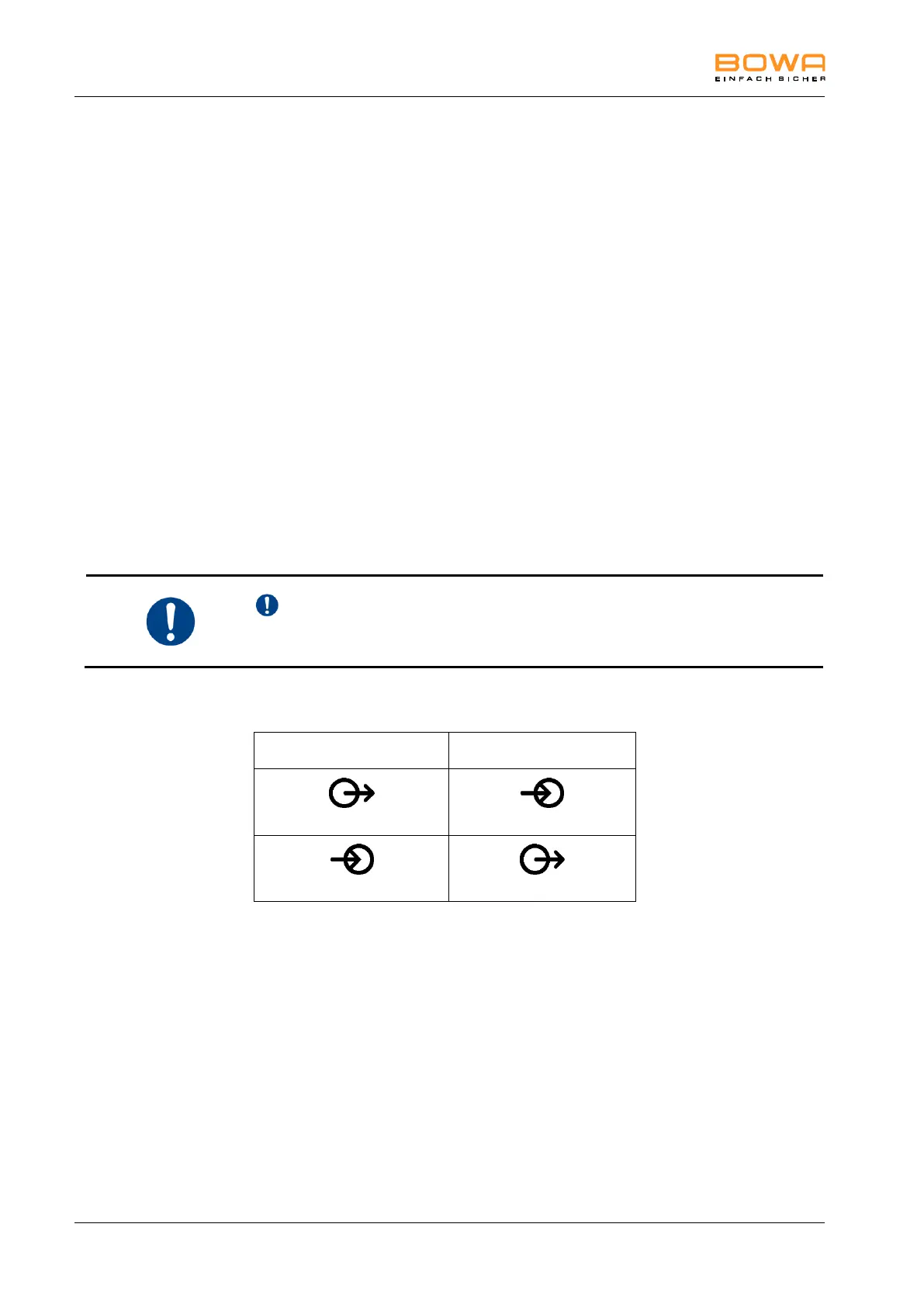
Signal connector on
ARC PLUS
Signal connector on
ARC 350/400
A foot switch is necessary for using the operating modes for flexible argon
application with the ARC generator. This switch must be connected to the rear
panel of the ARC generator.
Up to two gas bottles can be connected using pressure reducers
(e.g. 900-901).
Connect the quick-disconnect coupling on the end of the hose from the
pressure reducer to either connector 12 or connector 14 on the ARC PLUS.
Always use connector 11 for the electronic pressure sensor of the pressure
reducer connected to connector 12. Output 14 corresponds to connector 13.