85
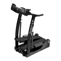
3. Disconnect the Cable Connector from the
Resistance PCB.
Note: Be sure to note how the cable attaches for re-
assembly. If the Cable Connectors are secured by a
small amount of glue, use a pair of small nose pliers to
grab and remove the glue.
NOTICE: Do not cut or pinch the cables.
4. Using a #2 Phillips screwdriver, remove the screws
that attach the Resistance PCB to the Frame
Assembly.
5. Using a #2 Phillips screwdriver, attach the new
Resistance PCB to the Frame Assembly.
6. Connect the Cable Connector to the new
Resistance PCB.
NOTICE: Do not cut or pinch the cables.
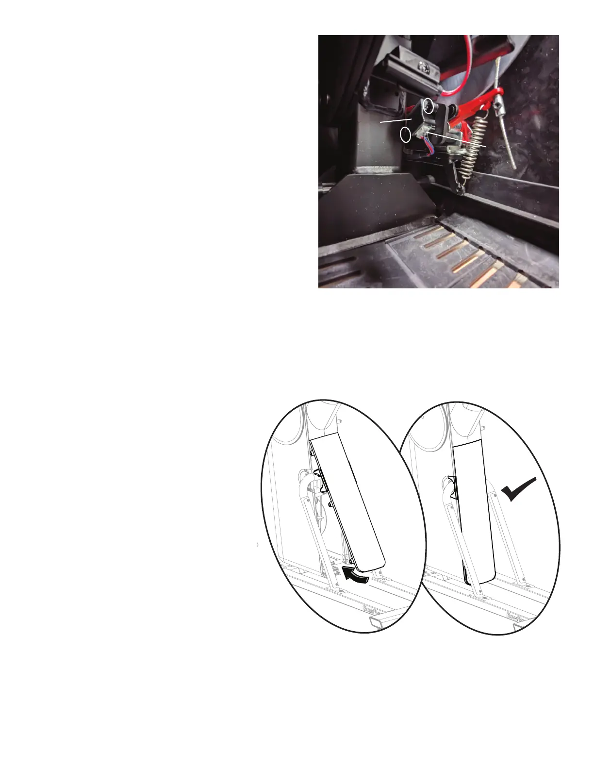
7. Re-install Rear Shroud to the Frame Assembly.
Place the upper part of the Rear Shroud onto the
Frame Assembly, and then pivot it downward into
place. There are 6 tabs that will secure it.
Cable Connector
Resistance
PCB