95
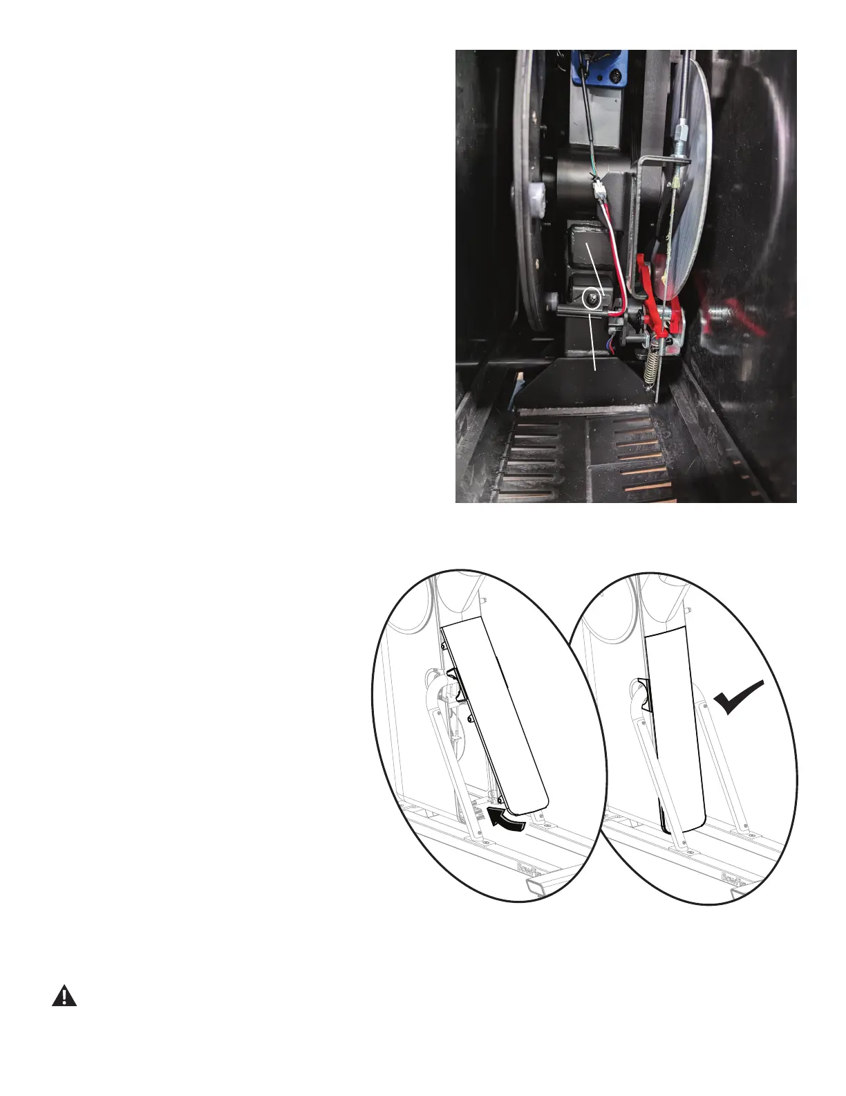
3. Using a #2 Phillips screwdriver, remove the 1 screw
(indicated by oval) that attaches the Speed Sensor
Mount to the Frame Assembly.
4. Remove the Speed Sensor Assembly from the old
Speed Sensor Mount.
NOTICE: Do not cut or pinch the cables.
5. Slide the Speed Sensor Assembly into the new
Speed Sensor Mount.
NOTICE: Do not cut or pinch the cables.
6. Using a #2 Phillips screwdriver, attach the new
Speed Sensor Mount to the Frame Assembly.
7. Re-install Rear Shroud to the Frame Assembly.
Place the upper part of the Rear Shroud onto the
Frame Assembly, and then pivot it downward into
place. There are 6 tabs that will secure it.
Speed
Sensor
Mount
Speed
Sensor
8. Final Inspection
Inspect your machine to ensure that all hardware is
tight and components are properly assembled.
Do not use until the machine has been fully
assembled and inspected for correct perfor-
mance in accordance with the Owner’s Manu-
al.