11
GB
screws and screw anchors supplied (fig. 5, 6, 7).
WARNING. For the unit to work properly, we
recommend you install it on a flat surface, being
careful not to overtighten screws.
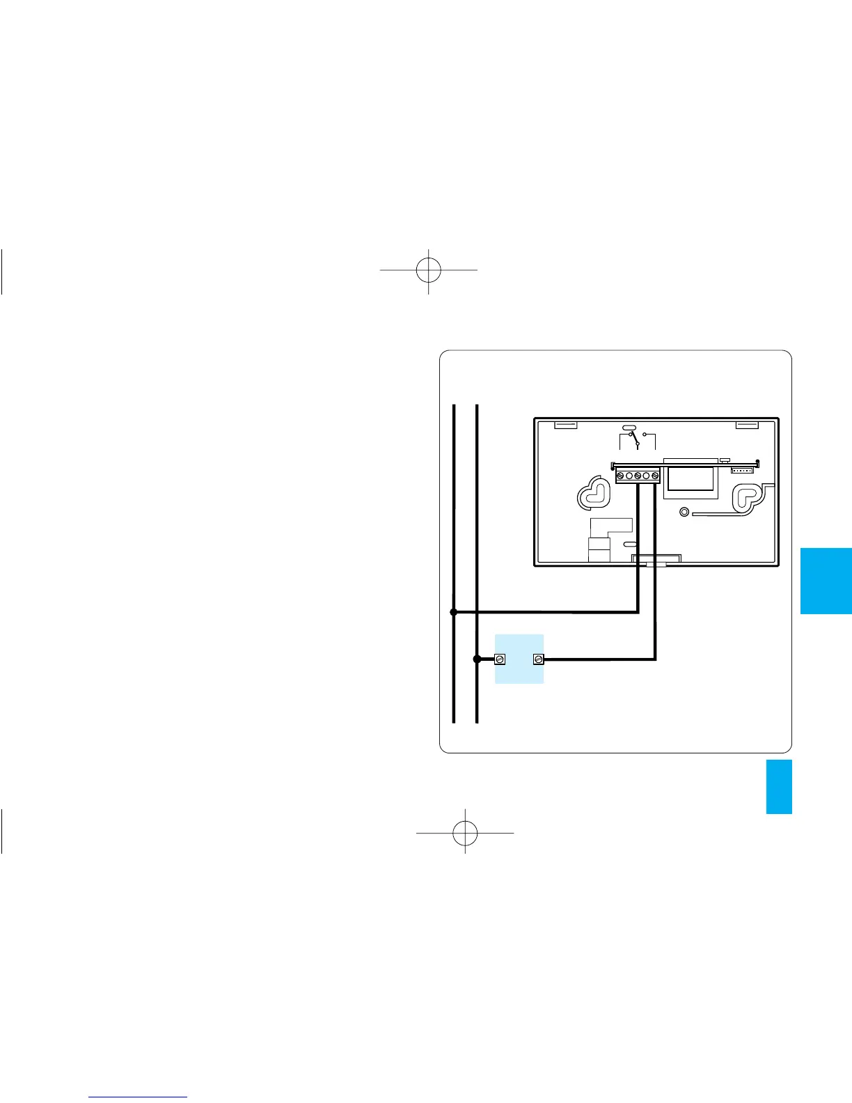
ELECTRIC CONNECTIONS
Wiring will depend on the type of equipment con-
trolled by the thermostat: refer, therefore, to the
diagram in fig. 8 or fig. 9. Refit the terminal cover.
KEY
Mains power supply wires
L = phase
N = neutral
Relay contacts
NA = normally open contact
C = common
NC= normally closed contact