GB
12
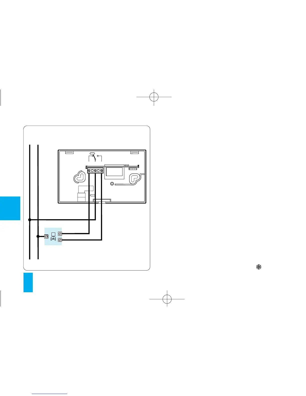
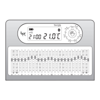
Loads
U1= burner, circulation pump, solenoid valve etc.
U2= motorized valve
3 - POWER SUPPLY
Insert three LR6 1.5 V penlight AA alkaline batte-
ries, respecting polarity indicated on the bottom
of the housing (fig. 10).
WARNING. Inserting the batteries the wrong
way round can damage the unit.
If the messages on the display do not appear
within 30 seconds, press the reset button R.
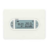
Once the batteries have been inserted, the dis-
play comes on, featuring the indications illustra-
ted in fig. 12.
Close the unit, making sure the fasteners fit in the
relevant slots (fig. 11).
The unit is now set to operate in automatic mode
AUT and with the heating program .