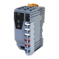
X20 system
3.4 Wiring
In order to achieve secure contact in the terminal blocks, wires must be stripped accordingly.
Figure 8: X20 system - Wiring
Notice!
The wire stripping length must not be more or less than 7 to 9 mm.
To avoid damaging the push-in terminals, the X20AC0SD1 B&R screwdriver should be used.
Order number Short description Figure
Screwdriver
X20AC0SD1 B&R screwdriver
Table 3: X20AC0SD1 - Order data
3.4.1 Shielded lines
Shielded lines for guaranteeing disturbance-free operation are essential for many applications, for example:
•
Fieldbus modules (Ethernet, POWERLINK, X2X Link, CAN bus, etc.)
•
reACTION Technology modules
•
Analog modules (inputs and outputs)
•
Counter modules/functions
•
PWM outputs
•
Safety technology (safety modules)
•
Temperature measurement modules
•
Motor control
•
ACOPOSinverter
•
etc.
For all details regarding wiring in accordance with regulations, see the respective user's manual. If not described
otherwise, grounding on both sides is preferred. A shield connection on both sides generally provides optimal
damping of all coupled interference frequencies.
The use of a shield connection on only one side is not permitted with potential differences. Possible potential
differences must be prevented using an equipotential bonding conductor.
Installation / EMC guide 1.36 (April 2021) 15

 Loading...