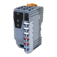
X67 system
4.3 Wiring
4.3.1 Basic information
Due to the high degree of flexibility, a few things must be taken into consideration:
•
Maximum number of 253 X67 modules in one X2X line
•
Maximum distance between X67 modules
•
Distance between the system supply modules
•
Station number assignment
•
Permissible current consumption
•
Corresponding bus termination
•
Use of suitable connectors for the X67 system
(for details, see the user's manual)
Possibilities for wiring the X67 system:
•
X2X Link power supply with X67 system supply, X67 bus controller or X20 bus transmitter
•
Isolated X2X Link and I/O power supply
•
Creating potential groups
4.3.2 Shielding and grounding
When using standard cables available from B&R, the cable shield is brought into the X67 module via the connector
(complete 360° shielding). Inside the X67 housing, all components including the base plate make contact with the
same ground. The final link in the chain is the mounting screw, which connects the base plate and the machine
part / mounting plate and completes the seamless ground contact from the cable to the machine part / mounting
plate. A contact with good conductivity between the X67 module base plate and the machine part / mounting plate
is absolutely required.
Figure 21: X67 system - Shielding and grounding
Notice!
The shielding at both ends of the cable must be professionally grounded on field-assembled cables!
26 Installation / EMC guide 1.36 (April 2021)

 Loading...