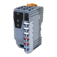
X67 system
4.2 Installation
X67 modules can be installed in several different ways:
•
Installation on a profile
•
Top-hat rail installation
•
Direct installation
Notice!
Since electromagnetic disturbances are deflected via the base plate on the back, it is important to
ensure that the mounting location has good conductivity!
The mounting location must also be connected with ground potential with good conductivity.
Attaching an X67 module
The thickness of the base plate (1.5 mm) should be taken into consideration when defining the screw length.
The grooved imprint in the base plate ensures that the screws do not become loose, even without an additional
retaining ring.
The recommended tightening torque for the M4 screw is 0.6 Nm.
Figure 17: X67 system - Fastening an X67 module
4.2.1 Installation on a profile
Installation here usually takes place with two sliding blocks and M4 screws.
Figure 18: X67 system - Installation on a profile
Notice!
For coated or anodized surfaces, the isolating coated or anodized layer in the area of the base plate
for X67 modules must be removed.
Installation / EMC guide 1.36 (April 2021) 23

 Loading...