X20 system
3.4.1.1 B&R cable recommendations
Cables available from B&R are recommended for wiring. All available designs and lengths can be found in the
user's manual or on the B&R website.
For example: Ethernet/POWERLINK
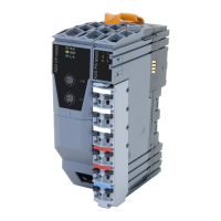
Figure 9: X20 cables
(B&R model number: X20CA0E61.xxxxx, length specifications: 0.2 m (xxxxx = 00020) to 20 m (xxxxx = 02000)).
The following wiring guidelines must be observed:
•
Use CAT 5 SF/UTP industrial data cables.
•
Observe the minimum cable bend radius (see data sheet for the cable).
•
Fasten the cable underneath the bus controller. The cable must be fastened vertically under the female
RJ45 connector on the bus controller.
•
The customer must implement additional measures in the event of further requirements.
3.4.1.2 Shield connection
The following points must be observed:
•
The ground connection should be made as short as possible with good conductivity.
•
Shield connection clamps allow the shield to be applied on special shielding brackets underneath the con-
troller.
•
Observe the bend radius.
•
Clamp to the backplane (optional).
To reduce EMC emissions as much as possible, the area where the wires are stripped must be kept as short as
possible (extend the cable shield as far as possible).
Figure 10: X20 cable shield
B&R recommends always solidly connecting the shield to a well-grounded and good conductive backplane using
shielding clamps combined with the X20 shielding brackets accessories.
16 Installation / EMC guide 1.36 (April 2021)
 Loading...