2
Install your new Braeburn thermostat in 5 basic steps:
1 *OTUBMMUIF4VC#BTF
2 1SPWJEF1PXFS
3 $POOFDU:PVS8JSFT
4FU*OTUBMMFS4XJUDIFT
5 "UUBDI5IFSNPTUBUUP4VC#BTF
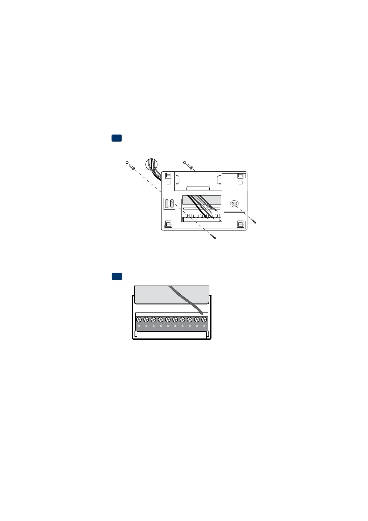
Install the Sub-Base:
t3FNPWFUIFTVCCBTFGSPNUIFCPEZPGUIFUIFSNPTUBU
t.PVOUUIFTVCCBTFBTTIPXOCFMPX
1
NOTE: After sub-base installation, you may insert the quick reference card
into the slot on the top of the base.
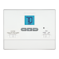
Provide Power
tFor 24 Volt AC powerZPVNVTUDPOOFDUUIFDPNNPOTJEFPGUIFUSBOT
GPSNFSUPUIF$UFSNJOBMPOUIFUIFSNPTUBUTVCCBTF
tFor primary or back-up powerJOTFSUUIFTVQQMJFEi""wUZQFBMLBMJOF
CBUUFSJFTJOUPUIFCBUUFSZDPNQBSUNFOUMPDBUFEJOUIFSFBSIPVTJOHPGUIF
UIFSNPTUBU.BLFTVSFUPQPTJUJPOUIF1PTJUJWFBOE/FHBUJWFTJEFT
PGUIFCBUUFSJFTDPSSFDUMZXJUIUIFTZNCPMTJOUIFCBUUFSZDPNQBSUNFOU
24VAC Power
Terminal (C)
2
Drill 3/16” pilot holes in
your desired location.
Use supplied anchors for
drywall or plaster.
UP UP
C