Factory Setting
Switch Default Options Comments
5
Heat Pump Systems (cont.)
NOTES - Heat Pump Systems
[1]*GCBUUFSJFTBSFJOTUBMMFEUIF7PMU"$DPNNPODPOOFDUJPOJTPQUJPOBM
[2]4FMFDUOGPSDPPMBDUJWFPS BGPSIFBUBDUJWF
[3]*OTUBMMBmFMETVQQMJFEKVNQFSCFUXFFOUIFW2 and EUFSNJOBMTJG
UIFSFJTOPTFQBSBUFFNFSHFODZIFBUSFMBZJOTUBMMFE
Provide disconnect and overload protection as required.
$0/7)1 $0/7
'$ '
)&)( )(
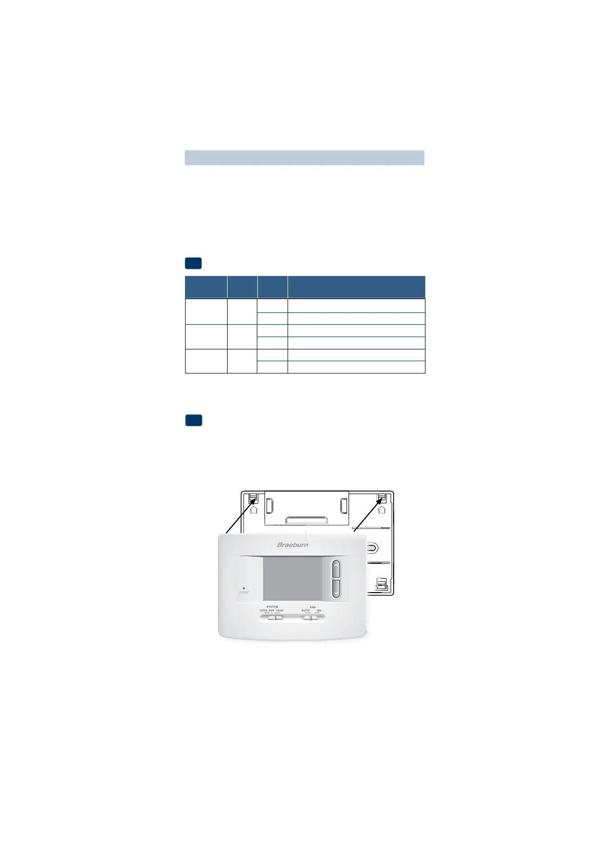
Set Installer Switches
4
$0/7 4FMFDUGPSDPOWFOUJPOBMTZTUFNT
)1 4FMFDUGPSIFBUQVNQTZTUFNT
' 4FMFDUGPSGBISFOIFJUUFNQFSBUVSFTDBMF
$ 4FMFDUGPSDFMTJVTUFNQFSBUVSFTDBMF
)( 4FMFDUGPSHBTIFBU
)& 4FMFDUGPSFMFDUSJDIFBU
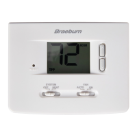
Attach Thermostat to Sub-Base
5
-JOFVQUIFUIFSNPTUBUCPEZXJUIUIFTVCCBTF
$BSFGVMMZQVTIUIFUIFSNPTUBUCPEZBHBJOTUUIFTVCCBTFVOUJMJUTOBQT
JOUPQMBDF
*OTFSURVJDLSFGFSFODFDBSEJOUPTMPUPOUPQPGUIFSNPTUBU
NOTE: Installer switches are located on the back of the thermostat. The
reset button must be pressed after making any changes to these switches.
UP UP