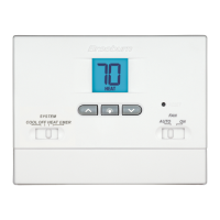
FEATURES
SPECIFICATIONS
1
2
2
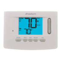
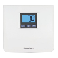
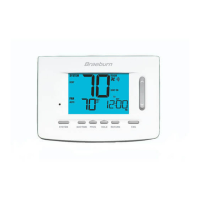
• Contemporary Styling with Large LCD Display
• Battery Powered (2 AA Alkaline batteries included)
• Relay Output for Maximum Compatibility
• LCD Display Backlight
• Easy Access Front Battery Door
• Compressor Short Cycle Protection
• Adjustable Temperature Differential
• Low battery Indication
• Quick Wiring Terminal Block
• High Temperature Safety Switch
• Low Temperature "Freeze" Protection
• Electrical Rating: 24 Volt AC (18-30 Volt AC)
1 amp maximum load per terminal
2 amp total maximum load (all terminals)
• Control Range: 45˚ - 90˚ F (7˚ - 32˚ C)
• Accuracy: +/- 1˚ F (+/- .5˚ C)
• DC Power: 3.0 Volt DC (2 AA Alkaline batteries included)
• Compatibility with low voltage single stage gas, oil or electric heating or cooling
systems, including single stage heat pumps. This thermostat can also be used on
250mv to 750mv millivolt heating only systems.
• Terminations: Rc, Rh, G, W, Y, B, O
INSTALLATION
3
3.1
Replacing Existing Thermostat
1.
Always turn off power to the air conditioning or heating system prior to removing existing
thermostat.
2.
Remove the cover of your old thermostat and locate the wire terminals. Do not remove
wires from terminals yet.
3.
Using small pieces of masking tape label wires prior to removal from terminals. Use the
chart below to determine the new terminal designations for your new thermostat.
4.
After labeling and removing all wires from terminals, unscrew the existing thermostat
mounting base from wall. Make sure to secure wires to prevent them from slipping
back into the hole in the wall.
NOTE: This thermostat is designed for use with a 24 Volt-AC low voltage single-
stage gas, oil or electric heating or cooling systems, including single sta ge heat
pumps. This thermostat can also be used on 250mv to 750mv millivolt heating only
systems. Do not use this thermostat on applications with voltages above 30 Volts AC.
Old Terminal from New Terminal for
Existing Thermostat New Thermostat Terminal Description
V or Rc Rc Cooling Transformer
M, 4, Rh, or R Rh Heating Transformer
G or F G Fan Control
H, W or 4 W Heating Control
Y Y Cooling Control
B B Reversing Valve (Heating)
O O Reversing Valve (Cooling)
C None-Cap the wire 24 Volt AC, Transformer Common
3
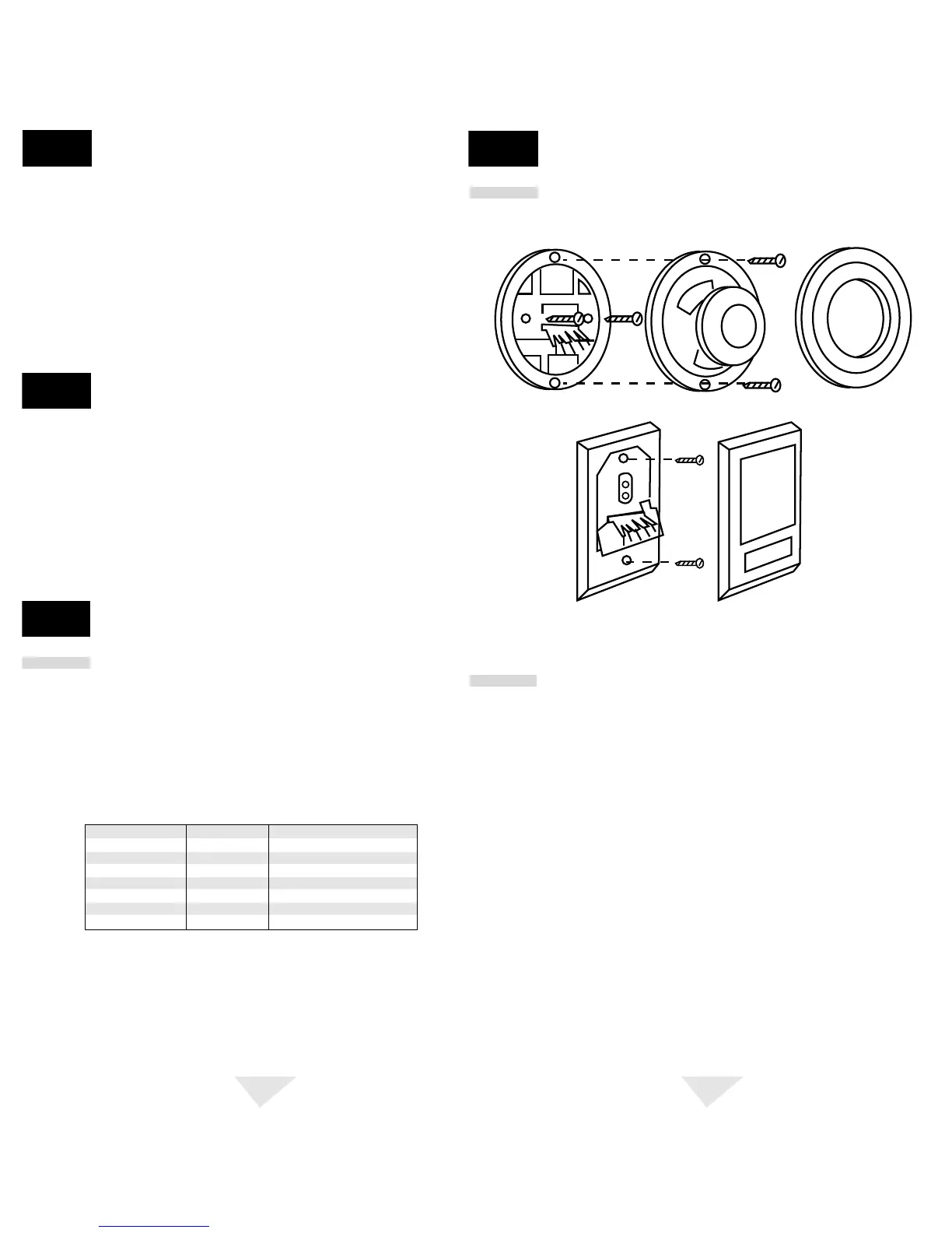
INSTALLATION
3
3.1
Replacing Existing Thermostat cont.
3.2
Installing Your New Thermostat
NOTE: If you are installing this thermostat in a new installation be sure to locate
the thermostat 4 to 5 feet above the floor in accordance with applicable building
codes. Make sure to install the thermostat in a location that provides good airflow
characteristics and avoid areas behind doors, near corners, air vents, direct sunlight
or near any heat generating device. Installation in an y of these areas could impact
thermostat performance.
1.
Always turn off power to the air conditioning or heating system prior to installing your new
thermostat.
2.
Place system switch on front of thermostat to OFF position.
3.
Place fan control switch on front of thermostat to AUTO position.
4.
Remove front of thermostat body from rear body by pressing release latch on bottom of
front body.
5.
Place the thermostat rear body (mounting plate) against wall in the desired thermostat
location.
6.
Guide thermostat wires through center hole in rear body. Continue to hold rear body
against wall.
7.
Mark placement of mounting holes as appropriate and drill using a 3/16" drill bit.
8.
Gently tap supplied plastic anchors into the holes in the wall.
9.
Place the thermostat rear body (mounting plate) against the wall in the desired location
making sure the mounting holes are aligned as appropriate and the thermostat wires
are properly inserting through opening in middle of rear body.
cont.
Illustration of round and rectangular
mechanical thermostat exploded views.

 Loading...