INSTALLATION AND SERVICE OPERATIONS OPA-100
INSTALLATION AND SERVICE OPERATIONS 9/22 MS0100-06-0_service_manual.doc
3.3.2 INTERNAL VISUAL CHECK (ONLY FOR AUTHORIZED TECHNICIAN)
DANGER!
TO AVOID BURN ON YOUR HANDS DO NOT TOUCH UNCOVERED PARTS OF
MEASUREMENT CHAMBER
TO AVOID CRUSHING YOUR FINGERS DON’T TOUCH THE ZERO ELECTROVALVE
WHEN POWER SUPPLY IS ON
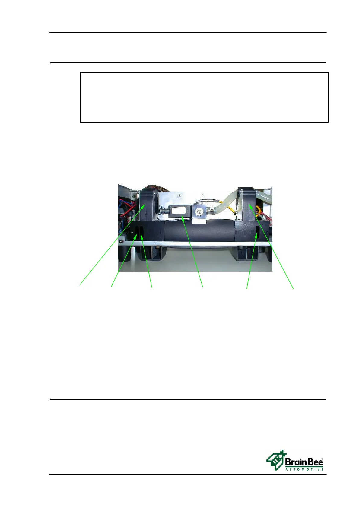
• Remove the cover by unscrewing the eight black screws.
• Check the integrity of pneumatic and electric circuits.
Fan (side rx light) - empty frame - frame with glass - zero electro valve - frame with glass – Fan (side tx light)
Run software of Smokemeter and wait for warm-up to finish.
After warm-up, the OPA-100 performs an autozero adjustment.
During the autozero adjustment the electro valve turn on and the two fans will start .
Check the fans turn properly.
The red led on the electronic board flashes 1 pulse/sec to signal a correct working status.
If led flashes slow (1 pulse/3 sec) OPA-100 is waiting for communication with PC.
If led flashes fast (5 pulse/1 sec) the OPA-100 signals a warning state with an internal
error.
To view internal errors, from the Smokemeter menu select F6 (Control) and then F8
(Status OPA-100).
3.3.3 CHECK POWER SUPPLY
Check the power supply voltage and frequency at the location of use to determine compliance
with the specifications on the measuring instrument’s label.
The OPA-100 power supply range must be from 11 to 15 VDC.
You can measure power supply voltage value by a voltmeter between pin 1(+) and 4(-) of
the OMNIBUS CABLE connected to the power supply.