Do you have a question about the Brauniger ALPHAMFD and is the answer not in the manual?
Critical safety warnings regarding the ALPHAMFD's certification and user responsibility.
Instructions and dimensions for physically installing the ALPHAMFD into the aircraft cockpit.
Guidelines and warnings for making electrical connections to the ALPHAMFD.
Procedure for deactivating unused temperature sensor ports to suppress 'nonsense' values.
Detailed wiring diagram showing sender connections to the ALPHAMFD unit.
Pin assignment and function of the ALPHAMFD connection board.
Instructions for installing the fuel flow sender for accurate fuel measurement.
General guidelines for mounting the fuel flow sender.
Critical safety precautions for mounting the fuel flow sender to ensure correct operation.
Tips for ensuring accurate fuel flow readings.
Visual guide illustrating the correct mounting position for the fuel flow sender.
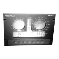
How the ALPHAMFD displays indicated and calibrated air speed.
Steps and warnings for calibrating the air speed indicator for accuracy.
Explanation of different speed display resolutions and unit conversions.
Configuration and function of the stall warning alarm.
Configuration and function of the 'Velocity Never Exceed' warning alarm.
Setting and reading altitude (MSL, AGL) and air pressure (QNH, QFE, QNE).
How to use the Altitude Guidance Mode for maintaining a set altitude.
Display and interpretation of vertical speed (climb/sink) data.
Description of the single pointer display option for the VSI.
Description of the sector display option for the VSI.
How the ALPHAMFD records and displays flight duration and timing.
How to display temperature and voltage readings, and unit selection.
Setting and displaying the current time and date.
Display and configuration of engine revolutions per minute (RPM).
Details on connecting and configuring RPM measurement from engine ports.
Tracking total engine running time and per-flight engine hours.
Monitoring fuel levels, consumption rate, and state.
Installation and operation of the fuel flow meter, including safety warnings.
Factors affecting the precision of fuel flow measurements.
How to measure fuel flow using two senders in a fuel flow-back system.
Recommended method for measuring fuel flow with a single sender in a fuel flow-back system.
How to view fuel flow data on the ALPHAMFD display.
Procedure for calibrating the fuel flow meter for accuracy.
Understanding the fuel state bar graph and its indications.
Steps to input actual fuel quantity after refueling.
Monitoring CHT and EGT using Type K sensors.
Measuring and displaying engine water temperature.
Measuring and displaying engine oil temperature.
How to cycle through and view different temperature readings.
Monitoring oil pressure and receiving warnings for low/high pressure.
How the oil pressure switch functions for low pressure indication.
How to read oil pressure from an analogue sender.
Displaying aircraft system voltage and backup battery voltage.
Information about the integrated backup battery for power failures.
Accessing and reviewing recorded flight data and maximum values.
Overview of audible beeps and visual flashing alarms for various conditions.
Configuration and function of the stall warning alarm.
Warning for low aircraft power supply voltage.
Alarm indication for critically low fuel levels.
Detection and indication of temperature sensor connection failures.
Alarm for exceeding predefined engine temperature thresholds.
Audio warning system to help maintain a selected altitude.
Warning for oil pressure outside the normal operating range.
Alarm for exceeding maximum engine RPM limits.
Handling of error codes generated during the power-on self-test.
Comprehensive list of error codes and recommended actions.
Features for preventing unauthorized use and setting passwords.
How to change display units for various parameters.
Information on upgrading the ALPHAMFD software.
Procedure to reset all settings to their default factory values.
Detailed list and explanation of available SET-Mode configurations.
Engine-specific data for Rotax 582, including sensor connections.
Engine-specific data for Rotax 912 series, including sensor connections.
Engine-specific data for Rotax 503, including sensor connections.
Usage considerations and recommendations for flex-wing ultralights.
Information on the EL-backlight illumination, connection, and usage.
| GPS | Yes |
|---|---|
| Variometer | Yes |
| Altimeter | Yes |
| Airspeed Indicator | Yes |
| Data Logging | Yes |
| Interfaces | CAN, RS232 |
| Certification | EASA |