SERIES 54 PROXIMITY SENSORS
Installation, Operation, and Maintenance Manual
13 of 28© 2022 BRAY INTERNATIONAL, INC. ALL RIGHTS RESERVED. BRAY.COM The Information
contained herein shall not be copied, transferred, conveyed, or displayed in any manner that would
violate its proprietary nature without the express written permission of Bray International, Inc.
540022-71104533
5-30V DC / 100mA
DC 2-Wire PNP/NPN
3
4
L+
L-
L+
1
L-
I
II
2
I
II
I II
Made in Czech Republic
R
540022-71104533
5-30V DC / 100mA
DC 2-Wire PNP/NPN
3
4
L+
L-
L+
1
L-
I
II
2
I
II
I II
Made in Czech Republic
R
540022-71104533
5-30V DC / 100mA
DC 2-Wire PNP/NPN
3
4
L+
L-
L+
1
L-
I
II
2
I
II
I II
Made in Czech Republic
R
R
IND.CONT.EQ.
57M3
12
540041-71104533
DC 3-Wire PNP + Out
10-30 V DC / 100 mA
II I
Made in Czech Republic
valve
PWR
4
L-
SII
V-
V+
V+
V-
3
2
1
5
6
4
3
5
I
II
II
I
SI
L+
R
IND.CONT.EQ.
57M3
12
540041-71104533
DC 3-Wire PNP + Out
10-30 V DC / 100 mA
II I
Made in Czech Republic
valve
PWR
4
L-
SII
V-
V+
V+
V-
3
2
1
5
6
4
3
5
I
II
II
I
SI
L+
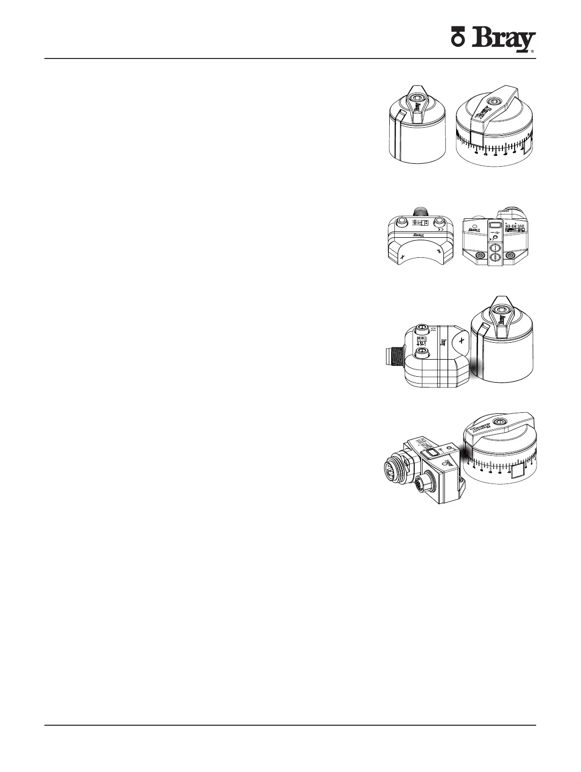
OPERATION OVERVIEW
Bray’s inductive sensors use a contactless indication system
designed to monitor the position of rotary devices An activator is
mounted onto the actuator center pinion As the valve is actuated
the open and close positions are measured by the rotation of the
activator The activator contains a metal insert that activates the
corresponding inductive switch in the sensor This activation is
relayed to the end user to validate valve position
Operations
Bray’s S Sensors contain two proximity switches in a
hermetically sealed housing Location of switches are designated
by a “” or roman numerals I and II
Based on the position of the pinionactivator one of the metal
inserts on the activator will be directly in front of the switch
When the valve is open one of the metal inserts is directly in
front of the sensor This signals the end user of an open signal
and illuminates the corresponding LED When the valve is closed
the other metal insert activates the second switch This signals
the end user a closed signal and illuminates the second LED The
function of each switch can be selected by the end user This can
be done by adjusting the activator to match the actuator position
(see Section ) or by configuring the PLC All activators can
be configured to be used for clockwise or counter-clockwise
valve operation
R
IND.CONT.EQ.
57M3
12
540041-71104533
DC 3-Wire PNP + Out
10-30 V DC / 100 mA
II I
Made in Czech Republic
valve
PWR
4
L-
SII
V-
V+
V+
V-
3
2
1
5
6
4
3
5
I
II
II
I
SI
L+
R
IND.CONT.EQ.
57M3
12
540041-71104533
DC 3-Wire PNP + Out
10-30 V DC / 100 mA
II I
Made in Czech Republic
valve
PWR
4
L-
SII
V-
V+
V+
V-
3
2
1
5
6
4
3
5
I
II
II
I
SI
L+
R
IND.CONT.EQ.
57M3
12
540041-71104533
DC 3-Wire PNP + Out
10-30 V DC / 100 mA
II I
Made in Czech Republic
valve
PWR
4
L-
SII
V-
V+
V+
V-
3
2
1
5
6
4
3
5
I
II
II
I
SI
L+
540022-71104533
5-30V DC / 100mA
DC 2-Wire PNP/NPN
3
4
L+
L-
L+
1
L-
I
II
2
I
II
I II
Made in Czech Republic
R
540022-71104533
5-30V DC / 100mA
DC 2-Wire PNP/NPN
3
4
L+
L-
L+
1
L-
I
II
2
I
II
I II
Made in Czech Republic
R
540022-71104533
5-30V DC / 100mA
DC 2-Wire PNP/NPN
3
4
L+
L-
L+
1
L-
I
II
2
I
II
I II
Made in Czech Republic
R
R
IND.CONT.EQ.
57M3
12
540041-71104533
DC 3-Wire PNP + Out
10-30 V DC / 100 mA
II I
Made in Czech Republic
valve
PWR
4
L-
SII
V-
V+
V+
V-
3
2
1
5
6
4
3
5
I
II
II
I
SI
L+
R
IND.CONT.EQ.
57M3
12
540041-71104533
DC 3-Wire PNP + Out
10-30 V DC / 100 mA
II I
Made in Czech Republic
valve
PWR
4
L-
SII
V-
V+
V+
V-
3
2
1
5
6
4
3
5
I
II
II
I
SI
L+
540022-71104533
5-30V DC / 100mA
DC 2-Wire PNP/NPN
3
4
L+
L-
L+
1
L-
I
II
2
I
II
I II
Made in Czech Republic
R
540022-71104533
5-30V DC / 100mA
DC 2-Wire PNP/NPN
3
4
L+
L-
L+
1
L-
I
II
2
I
II
I II
Made in Czech Republic
R
540022-71104533
5-30V DC / 100mA
DC 2-Wire PNP/NPN
3
4
L+
L-
L+
1
L-
I
II
2
I
II
I II
Made in Czech Republic
R
 Loading...