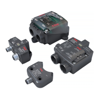
SERIES 54 PROXIMITY SENSORS
Installation, Operation, and Maintenance Manual
3 of 28© 2022 BRAY INTERNATIONAL, INC. ALL RIGHTS RESERVED. BRAY.COM The Information
contained herein shall not be copied, transferred, conveyed, or displayed in any manner that would
violate its proprietary nature without the express written permission of Bray International, Inc.
INTRODUCTION
All information within this manual is relevant to the safe operation
and proper care of your Bray product Please understand the
following examples of information used throughout this manual
The Series Proximity Sensor has been designed to provide
valve position indication utilizing various signal types Each of
these configurations will be covered in more detail on the pages
that follow
All Bray S Proximity Sensors utilize solid state switches
Although the solid state switch performs the same function as a
conventional mechanical switch there are dierences in the way
solid state switches operate
NOTICE
It is very important for the user to pay close attention to the
exact specifications of their sensor in order to avoid damaging
the unit
Solid state switches have current restrictions imposed by the
semi conducting materials used to form the sensor These
current limitations have to be accounted for during setup
Unlike mechanical switches which can normally handle several
amperes of current flowing through them solid state switches are
generally rated for half an ampere or less
NOTICE
The electrical characteristics of the S must be compatible with
the application
When working with the S several parameters must be
considered A few of which (with significant importance) are
listed here
> operating voltage
> maximum switching current
> output voltage drop
> residual current.
Using an S outside of these parameter limits can cause damage
to the unit and void factory warranty
Operating voltage is the amount of voltage necessary for the
sensor to operate The maximum switching current is the largest
amount of current that the sensor’s solid state electronics can
have flowing through them in the on-state (when the target is in
proximity of the sensor) During commissioning it is up to the
user to correctly apply the sensor to their control system in order
to limit the current flowing through the device All the necessary
information can be found in the technical manual

 Loading...