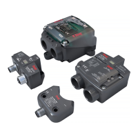
SERIES 54 PROXIMITY SENSORS
Installation, Operation, and Maintenance Manual
4 of 28© 2022 BRAY INTERNATIONAL, INC. ALL RIGHTS RESERVED. BRAY.COM The Information
contained herein shall not be copied, transferred, conveyed, or displayed in any manner that would
violate its proprietary nature without the express written permission of Bray International, Inc.
Introduction continued
Output voltage drop is defined as the amount of voltage that
will drop across the solid state switch This voltage drop will
often vary with the amount of current flowing through the sensor
and the load This drop in voltage becomes paramount when
connecting several proximity sensors in series each unit will have
a voltage drop across it – adding each subsequent drop and
subtracting from the supply voltage yields the resulting voltage
at the end of the series connection The user needs to ensure that
the supply voltage is large enough so that the resulting voltage
after all the drops is above the minimum operating voltage of
the last S in the series connection Sensors located a great
distance from the load require consideration as well as a general
rule every ft of wire will have a resistance of (see
electrical code references for the resistance value of specific wire
sizes) It is important for the customer to ensure that the distance
between the S and the control panel is not long enough to
cause the voltage drop to fall below the minimum operating
voltage of the sensor
Residual current is often referred to as leakage current In the
“o” state (target is NOT in proximity of the sensor) the sensor
draws a small amount of current in order to power the device’s
electronics This is necessary for the device to sense the target
at any point in time when the supply voltage is applied It is
important that this residual current is below the maximum o-
state current rating of the control system

 Loading...