SERIES 54 PROXIMITY SENSORS
Installation, Operation, and Maintenance Manual
9 of 28© 2022 BRAY INTERNATIONAL, INC. ALL RIGHTS RESERVED. BRAY.COM The Information
contained herein shall not be copied, transferred, conveyed, or displayed in any manner that would
violate its proprietary nature without the express written permission of Bray International, Inc.
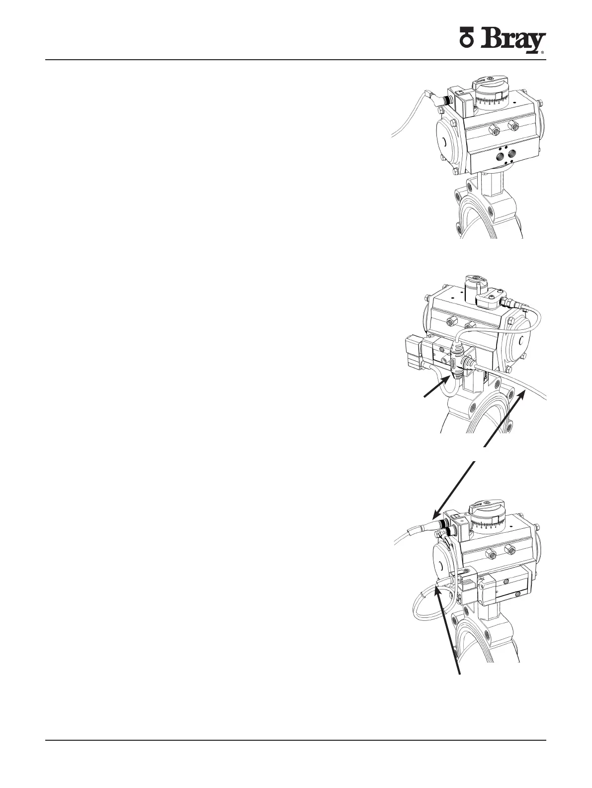
S-connector
Y-connector
System side
CONNECTIONS (OPERATION)
Bray oers three dierent connections to satisfy the customer’s
application requirements Each sensor’s pin connection is listed
in its respective technical manual Turn o all power and lockout
tag out service panel before installing or modifying any electrical
wiring
Sensor Only
Sensor connection supplies sensor power and signal output
Sensor and Solenoid (Shared)
Y-connectors are used to allow solenoid control on sensors
without dedicated solenoid outputs The system side line carries
both the sensor and solenoid power The system side line splits to
supply power and signal to sensor and solenoid
Sensor and Solenoid (Independent)
Bray also oers sensors with dedicated solenoid outputs In this
set up the sensor signal and solenoid power are transmitted on
the main system side line The solenoid is activated via power
supplied from the sensor through the S-connector S-connector
selection can be found in the sensor technical manual
Cable Gland Connections
M cable gland connections are found on the following sensors
-
-
-
- (included in Kit PN -xx)
In order to field-wire these models follow these guidelines
1. Take the sensor cover o. The cover should be kept on hand
for reference.
2. Wire the sensor as per the wiring diagram on the outside of
the sensor cover or technical specification sheet.
3. Close the cover and securely tighten cover screws
Range of wire size gauge acceptable
(single conductor per terminal)
General: 16 to 28AWG
Industrial: 14 to 22AWG
Hazardous: 14 to 22AWG

 Loading...