SERIES 54 PROXIMITY SENSORS
Installation, Operation, and Maintenance Manual
8 of 28© 2022 BRAY INTERNATIONAL, INC. ALL RIGHTS RESERVED. BRAY.COM The Information
contained herein shall not be copied, transferred, conveyed, or displayed in any manner that would
violate its proprietary nature without the express written permission of Bray International, Inc.
ADJUSTMENT
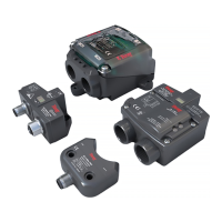
Adjusting the Activator
Adjustable activators are for customers that want the flexibility
to position their indication limits outside of the standard zero to
ninety degrees The three pieces of the adjustable activator can
be rotated in five degree increments To adjust follow the steps
below
1. Loosen the allen head bolt which holds the three pieces of the
activator on the pinion.
2. Rotate the relevant piece until the desired amount of travel is
achieved.
a Use the incremental degree marks on the activator for
reference
3. Ensure the yellow indicator is set to match the valve disc
position.
4. Tighten the allen head bolt.
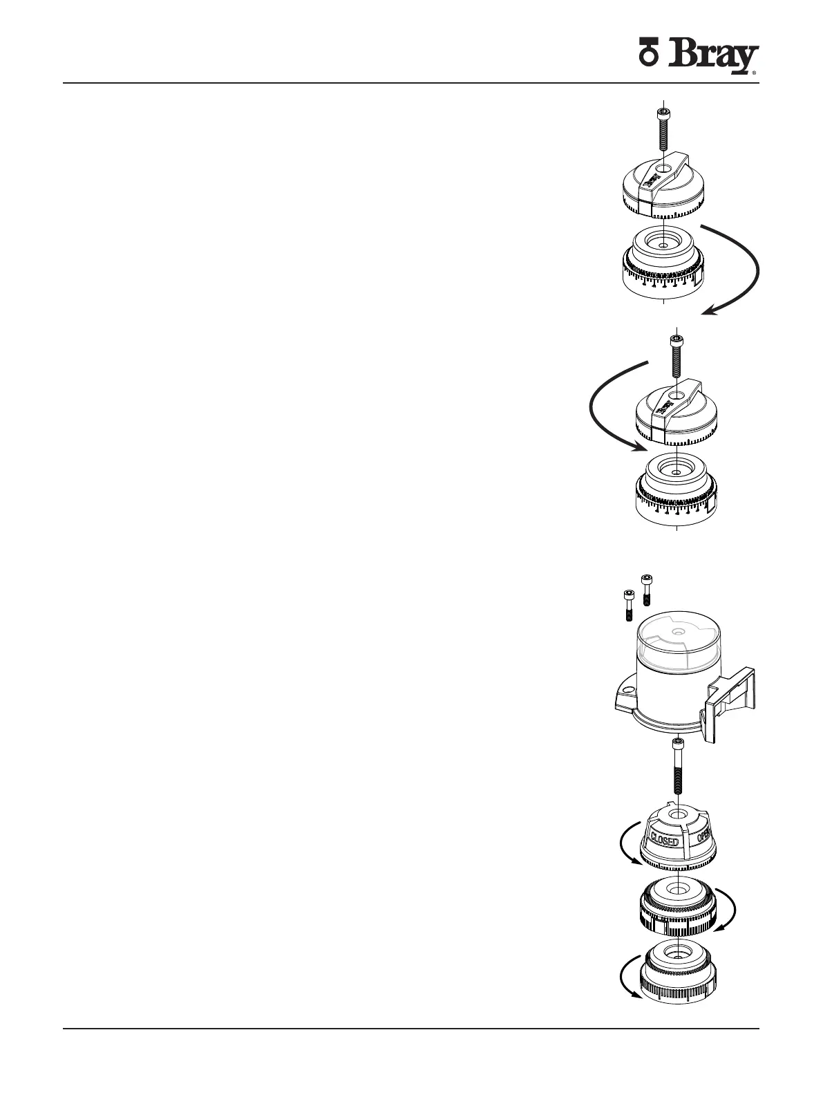
Adjusting the High Visibility Activator
1. Remove the two activator cover bolts.
2. Remove activator cover by pulling up and away from the
actuator.
3. Loosen center allen head bolt holding the activator to the
pinion.
4. Rotate the relevant piece of the activator until the desired
amount of rotation is achieved.
a Insure that the open and close activator is visible when
the cover shield is installed
5. Re-tighten the center allen head bolt locking the activator to
the pinion.
6. Install the cover and mounting bolts.
 Loading...