31
2
2
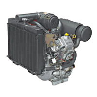
1. 0.5 Amp DC Only (Figure 8)
• Unregulated
• Output at 2800 RPM
• .5 Amps DC for charging battery
• One black lead (A) from stator
• White connector (B) output lead
Figure 8
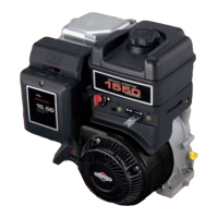
2. 14 Volt AC Only (Figure 9)
• 14 Volts AC for lighting circuit
• One black lead from stator (A)
• White connector (B) output lead
• Unregulated
Figure 9
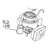
3. 3 Amp DC Only (Figure 10)
• 3 Amps DC unregulated for charging battery
• One red lead (A) from stator
• Diode encased at connector
• Red connector (B) output lead
Figure 10
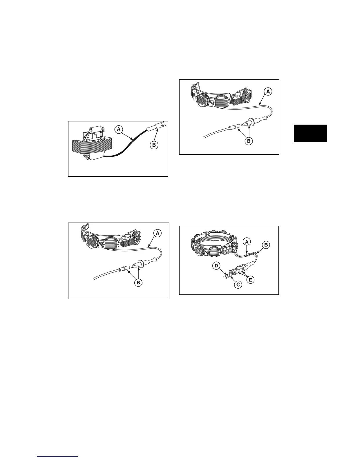
4. Dual Circuit (Figure 11)
• 3 Amps DC unregulated for charging
battery, red lead from stator (A)
• 14 Volts AC for lighting circuit, black lead
from stator (B)
• Diode encased at connector
• White connector (E) with two pin terminals
• White lead (D), AC current for lights
• Red lead (C), DC current for charging circuit
Figure 11
5. Tri-Circuit (Figure 12)
• Stator assembly (A)
• Black lead from stator (B)
• Connector (C)
• Two diodes encased in wiring harness (D)
• WHITE lead - 5 Amps DC (-) to lights (E)
• RED lead - 5 Amps DC (+) to battery, clutch
(F)