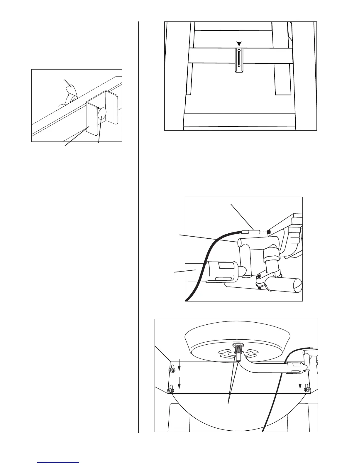
Step 18
Attach the tank bracket by inserting the
pre-attached carriage bolt through the
keyhole, slide down and then use the
wing nut to secure.
Step 19
Insert each main burner igniter lead wire
to each valve.
Step 20
Attach side burner assembly using four
M6 X 10 mm bolts, insert M6 X 10 mm
bolts halfway and then slide side burner
assembly down over bolts and tighten
securely.
Step 21
Loosen the two bolts with washers from
the bottom of the burner assembly
bracket. This will allow the burner to
move freely while performing Step 22.
Igniter Lead Wire
Valve
Burner
Burner Assembly/Bracket Bolts
31
Wing Nut
Tank Bracket
Carriage
Bolt
 Loading...