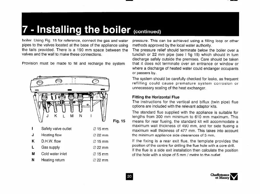
boiler. Using Fig. 15 for reference, connect the gas and water
pipes to the valves located at the base of the appliance using
the tails provided. There is a 190 mm space between the
valves and the wall to make these connections.
Provision must be made to fill and recharge the system
Fig. 15
Safety valve outlet
Heating flow
015mm
022mm
pressure. This can be achieved using a filling loop or other
methods approved by the local water authority.
The pressure relief should terminate below the boiler over a
tundish or 22 mm pipe (see I fig 15) which should in turn
discharge safely outside the premises. Care should be taken
that it does not terminate over an entrance or window or
where a discharge of heated water could endanger occupants
or passers by.
The system should be carefully checked for leaks, as frequent
refilling could cause premature system corrosion or
unnecessary scaling of the heat exchanger.
Fitting the Horizontal Flue
The instructions for the vertical and biflux (twin pipe) flue
options are included with the relevant adaptor kits.
The standard flue supplied with the appliance is suitable for
lengths from 300 mm minimum to 610 mm maximum. This
means for rear flueing, the standard kit will accommodate a
maximum wall thickness of 490 mm, and for side flueing a
maximum wall thickness of 477 mm. This takes into account
the minimum appliance side clearances of 5 mm.
K D.H.W. flow 015mm
If the fixing is a rear exit flue, the template provides the
L
Gas supply 022mm
position of the centre for drilling the flue hole with a core drill.
M
Cold water inlet 015mm
If the flue is a side exit installation then calculate the position
of the hole with a slope of 5 mm / metre to the outlet.
N Heating return 022mm