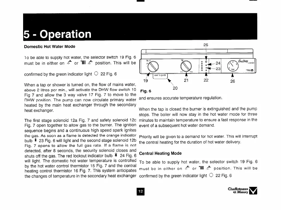
Domestic Hot Water Mode
To be able to supply hot water, the selector switch 19 Fig. 6
must be in either on k or ‘1111 .? position. This will be
confirmed by the green indicator light 0 22 Fig. 6
When a tap or shower is turned on, the flow of mains water,
above 2 litres per min., will activate the DHW flow switch 10
Fig 7 and allow the 3 way valve 17 Fig. 7 to move to the
DHW position. The pump can now circulate primary water
heated by the main heat exchanger through the secondary
heat exchanger.
The first stage solenoid 12a Fig. 7 and safety solenoid 12c
Fig. 7 open together to allow gas to the burner. The ignition
sequence begins and a continuous high speed spark ignites
the gas. As soon as a flame is detected the orange indicator
bulb 0 23 Fig. 6 will light and the second stage solenoid 12b
Fig. 7 opens to allow the full gas rate. If a flame is not
detected, after 8 seconds, the security solenoid closes and
shuts off the gas. The red lockout indicator bulb a 24 Fig. 6
will light, The domestic hot water temperature is controlled
by the hot water control thermistor 15 Fig. 7 and the central
heating control thermistor 16 Fig. 7. This system anticipates
the changes of temperature in the secondary heat exchanger
16
-\ $1 22 26
Fig. 6
20
and ensures accurate temperature regulation
When the tap is closed the burner is extinguished and the pump
stops. The boiler will now stay in the hot water mode for three
minutes to maintain temperature to ensure a fast response in the
event of a subsequent hot water demand.
Priority will be given to a demand for hot water. This will interrupt
the central heating for the duration of hot water delivery.
Central Heating Mode
To be able to supply hot water, the selector switch 19 Fig. 6
must be in either on
.e
or
‘Ill1
FF position. This will be
confirmed by the green indicator light 0 22 Fig. 6