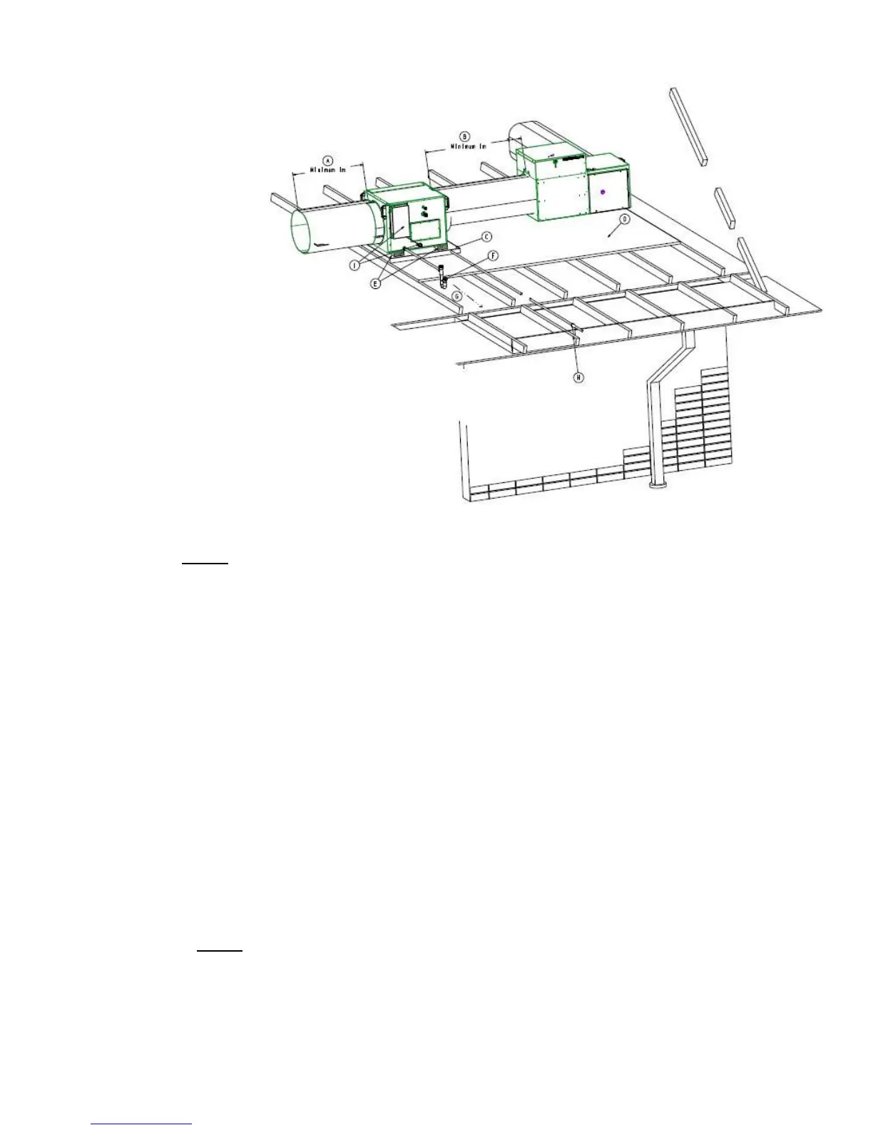
A. Ensure 1m minimum, or preferably 2½ times
the duct diameter, STRAIGHT duct length
before any take-offs occur
B. Ensure 1m minimum STRAIGHT duct
between the Gas Ducted Heater and ICE
coil unit
C. Safety Drain Tray (field supplied),
independently drained
D. Working Platform (field supplied)
E. Unit Supports (field supplied)
F. P Trap Assembly (supplied) on primary
condensate drain – fit as close as possible to
unit
G. Condensate drain pipe to be pitched down
and to be terminated in an approved manner
as specified by local codes
H. Terminate the Safety Drain Tray in a position
so as not to cause a nuisance, but where the
home owner can see if water is dripping.
Instruct owner to contact Installer or Brivis if
Safety Drain Tray outlet drips water
I. Electric box with standard 10 A power plug
• Run 3 core shielded communication cable
from indoor coil electric box (Terminals Q
,P, E) to the outdoor unit
• Run 24VAC from the heater into the indoor
coil electric box (Terminals A1, A2)
3.0 TYPICAL INSTALLATION
Fig. 6 - Typical Indoor Unit Installation
4.0 INDOOR UNIT INSTALLATION
• Indoor coils are supplied with a nitrogen holding charge ranging from 400kPa to 700kPa
• Connect a suitable pressure gauge to the indoor coil valve to ensure the internal pressure is at least 400kPa
• If the measured pressure is less than 400kPa, check and if necessary repair any leaks found before proceeding
• Remove the nitrogen holding charge by connecting a charging line with valve depressor
• For SWEAT connection: Sweat off the liquid & suction pipe blanking plates and proceed to pipe up in line with
section 6.0 (Refrigeration Charge & Pipe-work)
• For FLARE connection: Un-screw the flare connection, remove the plastic seal and proceed with section 6.0
(Refrigeration Charge & Pipe-work)
• Some heaters may require a transition to modify its starting collar (pop) size to suit the inlet pop size of the ICE
indoor coil. DO NOT REDUCE POP SIZES ON INDOOR COIL or HEATER
• Ensure minimum specified air quantity requirement passes through the ICE cooling coil at all times
• Ductwork and fittings must be sized to handle the total cooling airflow through the system on either whole home or
zoned basis
• 24 volt control wiring shall be installed from the indoor coil electric box (Terminals A1, A2) to the Heater (StarPro
series) or to Brivis Thermostat as required
• The electric box has standard 10 A power cord and plug , please do not cut or modify the cord
• 3 core shielded communication cable shall be installed from the indoor unit (Terminals Q, P, E) to the outdoor
unit. One end of the cable has to be earthed.
• If the Brivis Heater requires a remote thermistor installed in the supply air ductwork, position it in the supply air
starting collar (discharge pop) of the cooling coil (see Section 4.6)
.
 Loading...