4.1 Location
• Choose a location that is suitable for refrigeration piping and condensate drainage
• Allow adequate provision is made for service access
• Indoor Coil Unit is not weatherproof and should be installed so that there is no chance of direct sunlight, water or
moisture coming into contact with the outer casing
• Where the unit is installed in the roof or ceiling space ensure the building structure is capable of supporting the
unit’s weight – do not suspend unit from support handles
• Brivis Inverter ICE indoor units shall be installed only downstream and at least 1m distance from heater’s main
supply air outlet and always before the first duct branch-take-off fitting
• Never put the Indoor Coil Unit in the Return Air part of the duct system, this may result in condensation forming in
the Heater, causing corrosion and damage to vital components
• Ensure a minimum of 1m, or preferably 2½ times the duct diameter of straight ductwork, is installed immediately
downstream of the Indoor Coil Unit before any divergence or branch-take-offs occur. Failure to do so may
compromise airflow, system performance and reliability
.
4.2 Condensate Drain / Safety Tray
• A non-flexible drainpipe shall be installed for the primary condensate run-off with a continuous downward grade
away from the unit of not less than 1:50
• When the indoor unit is installed in a roof or ceiling space, an additional field-supplied Safety Drain Tray shall be
installed under the Indoor Unit
• Safety Tray must also be separately drained, arranged to terminate in a position where the home owner can see if
water is dripping from the outlet. Please instruct the end user to call their Installer or Brivis Service should they
notice water dripping from the Safety Tray drain outlet
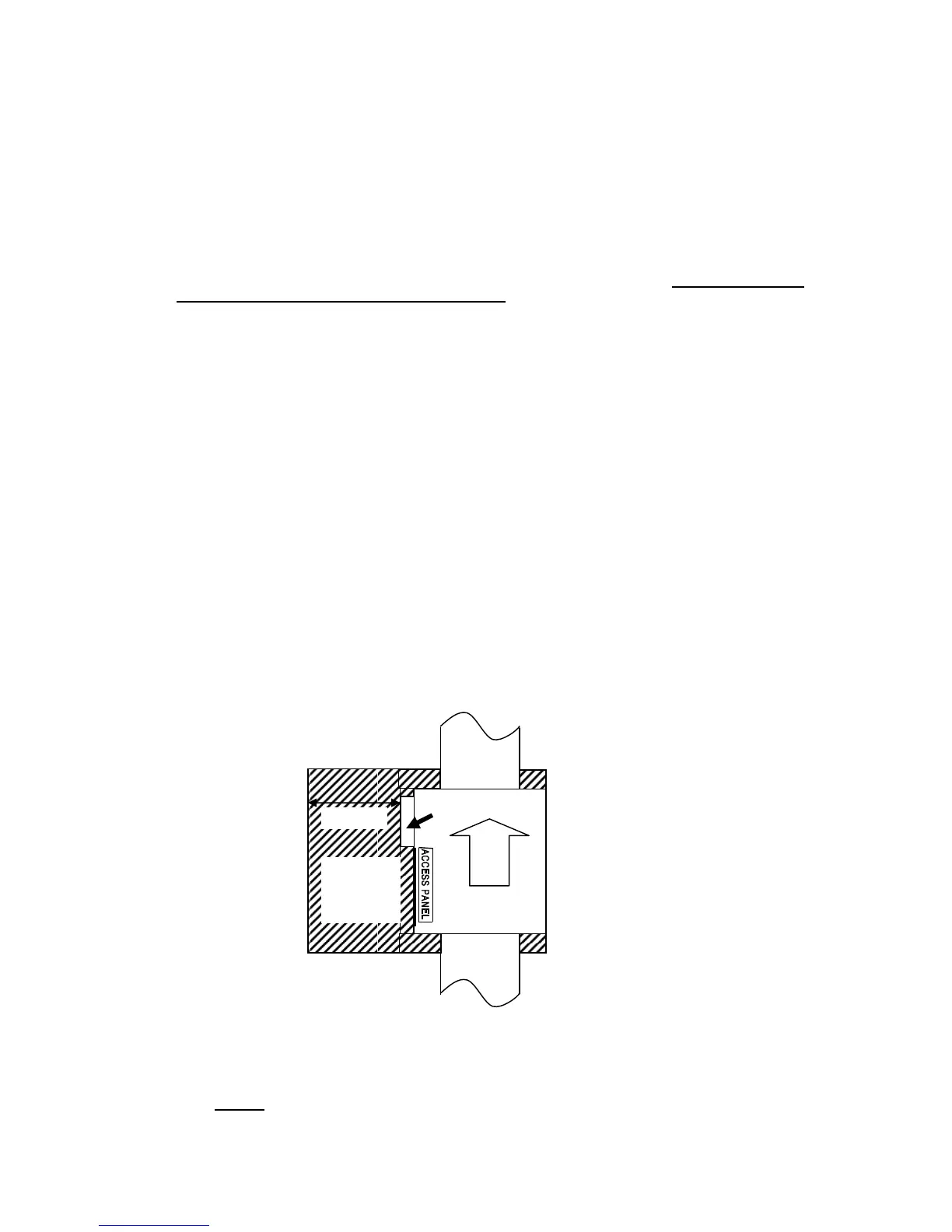
4.3 Minimum Service Access
For servicing, a minimum clearance of 600mm must be provided in front of the access panel side of the unit for its entire
length.
• Where installed on a platform in the roof space, the platform should also extend 600mm out in front of the access
panel side of the unit for its entire length
• A 600mm wide platform is required to connect between the indoor unit and the access opening or the ducted
heating unit for the purpose of access
• Adequate lighting should be installed, such as permanent artificial lighting with switch located at roof access
opening
• Duct work should not be installed across the platform preventing safe access
Fig. 7 - Indoor Service Clearances
4.4 Electrical Connection
• The electric box has standard 3 m, 10 A power cord and plug; do not cut or modify the cord
• 24 Volt control wiring shall be installed from the indoor coil electric box (Terminals A1, A2) to the Heater (StarPro
series) or to Brivis Thermostat as required
• 3 core shielded
communication cable shall be installed from the indoor unit (Terminals Q, P, E) to the outdoor
unit. One end of the cable has to be earthed.
AIR FLOW
PLATFORM
AND
SERVICE
CLEARANCE
REQUIRED
 Loading...