© 2023 Brivo Systems LLC. All rights reserved. PUB-Brivo ACS-SDC-E Installation Manual_v1.2
11
Brivo ACS-SDC-E Installation Manual
Wiring Procedures
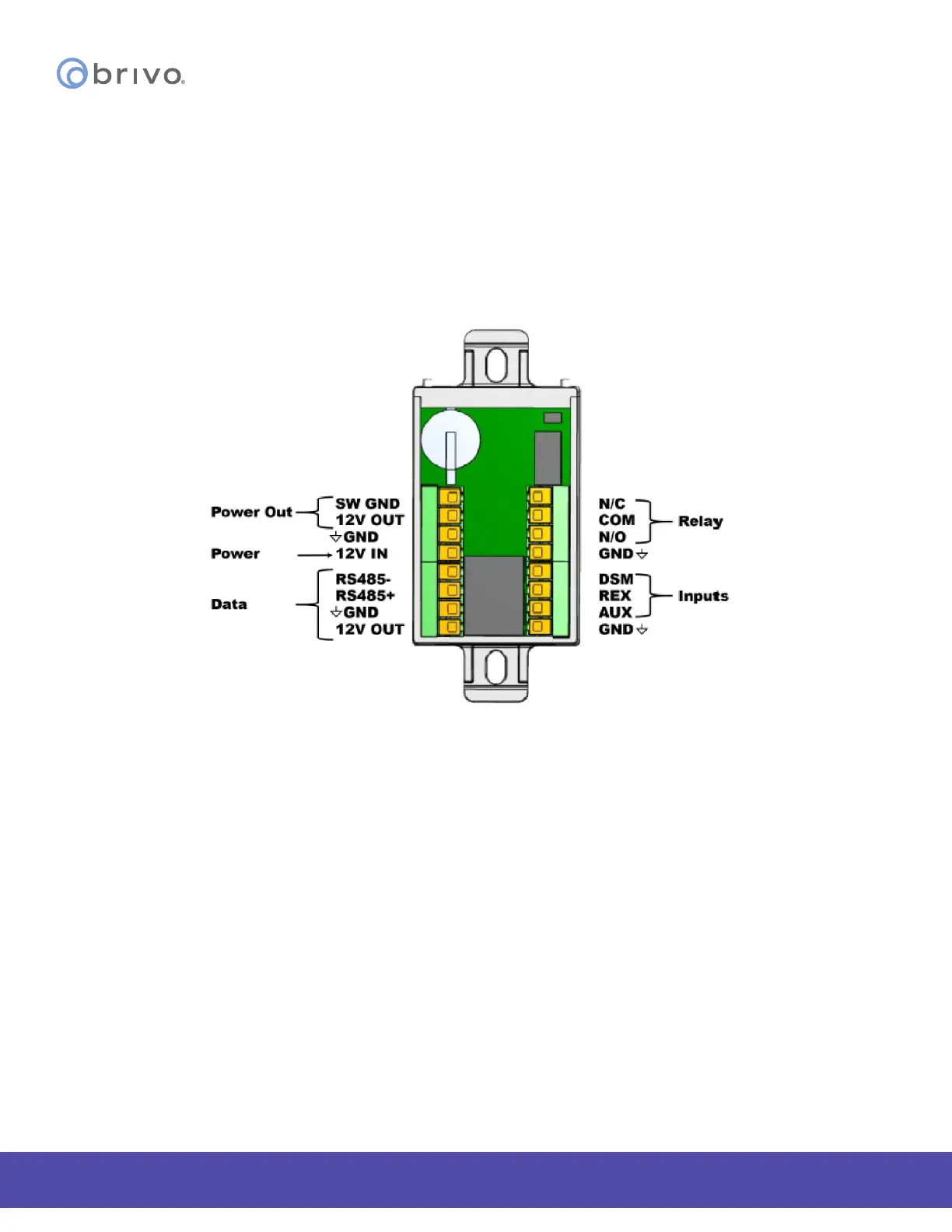
Provided below is the wire block diagram for the ACS-SDC-E unit.
NOTE: The ACS-SDC-E has a pair of RS485 wires for connecting up to two external OSDP readers. The
ACS-SDC-E can support one wired lock with up to two readers for use at one door for in/out antipassback
situations.
For the ACS-SDC-E unit to be used for controlling a door, make the following connections:
ACS-SDC-E Wire Block Diagram
Power In
1. DC Power In is rated from 10V DC to 15V DC. DC Power shall be provided through a UL294
approved Power Supply with Class 2 limited output.
2. Optionally power can be supplied through Power over Ethernet (PoE) through the RJ45 connector.
3. In the case of both DC power and PoE, the ACS-SDC-E will draw power from the DC power
source.
WARNING: Use of 24V DC
The Brivo ACS-SDC-E Single Door Controller should be powered from Power over Ethernet (PoE) or a 12V DC
power supply. Do NOT use 24V as input power to the ACS-SDC-E. The only place on the ACS-SDC-E that you
can connect 24V is the Normally Open or Normally Closed relay contacts.