Product Application Note ■ BCM5221
7/7/00 ■ BCM5220
Broadcom Corporation
5221/5220-AN01 Product Application Note, Revision R Page 6
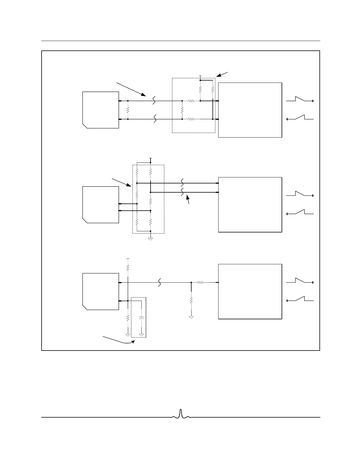
Figure 3: BCM5221 3.3V 100BASE-FX Interface
Figure 3 illustrates only the termination scheme for the 100BASE-FX interface. Refer to the fiber transceiver manufacturer’s
guidelines for transceiver power supply connection and filtering.
The TD+/- and RD+/- signal traces between PHY and the fiber transceiver should each be routed with a characteristic im-
pedance of 50Ω (100Ω differential) to match the termination network impedance given in Figure 3.
BRCM5221
Fiber
Transceiver
Signal Detect Termination
SD+
SD-
SD+
39.2Ω
1/16W
1%
221Ω
1/16
W
1%
512Ω
1/16
W
1%
487Ω
1/16
W
1%
The PHY RD+/- input
signals are level
shiftedtocreatea
common mode level
of 1.7V
Duetothestatic
nature of SD+, this
signal does not need
to be routed as a
controlled impedance
trace. Placement of
the dividing networks
is noncritical
3.3V
BRCM5221
Fiber
Transceiver
Receive Termination
RD+
RD-
RD+
RD-
130
Ω
1/16W
1%
130
Ω
1
/16W
1%
Route each signal
trace with a controlled
impedance of 50
Ω
if the
routing distance
exceeds one inch
12Ω
1/16W
1%
12Ω
1/16W
1%
68
Ω
1/10W
1%
68
Ω
1/10W
1%
3.3V
Place this termination
network close to the
BCM5228 input
BRCM5221
Fiber
Transceiver
100
Ω
1/16
W
5%
100
Ω
1/16W
5%
12.7
Ω
1/16W
1%
68.1
Ω
1/16W
1%
63.4
Ω
1/16W
1%
17.4
Ω
1/16W
1%
Transmit Termination
3.3V
If the trace length from PHY
to Fiber Transceiver is one
inch or less, the two 100
Ω
differential resistors can be
replaced by a single 50
Ω
differential resistor
Place this network
close to the Fiber
Transceiver input
TD+
TD-
Route each signal
trace with a controlled
impedance of 50
Ω
TD+
TD-
0.1uF
Cer 5%
Optional:
this cap is only
recommended in layouts
where noise sensitivity is
likely (ie long trace
connected to SD-)
The PHY SD+/-
input signals are
level shifted to
create a common
mode level of
1.7V