Broadcom Confidential 5880X-PS225-UG101
10
PS225 User Guide Quick Start Guide
3 Initial Board Setup and Connectivity
This section describes the initial board setup and connectivity.
3.1 PS225 Connector Locations
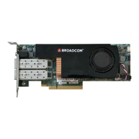
There are two SFP28 ports and a UART console port for the ARM CPU subsystem located on the I/O panel of the board
(see Figure 4).
Figure 4: PS225 Connector Locations
NOTE: The UART console is accessible via the round 3.5 mm jack on the I/O panel. The interface uses TTL-level signaling
and can be accessed using a widely available USB-to-TTL cable of type TTL-232R-3V3-AJ (based on FTDI chip).
3.2 Installing the PS225
To install the PS225:
1. Power down the host system and remove the AC power.
2. Insert the PS225 card into a PCIe 3.0 slot (at least x8 size) in the host system.
3. Connect one end of the SFP cable to port 0 or port 1 on the PS225 (see Figure 5).
4. Connect the other end of the SFP cable to an Ethernet switch that supports 10G or 25G Ethernet (see Figure 5).
NOTE: Both Ethernet ports must be connected to link partners operating at the same speed: either both 25GbE or both
10GbE. The ports do not support mixing 25GbE and 10GbE links.
5. Optionally:
a. Connect the other port of the PS225 card to an Ethernet switch (see Figure 5).
b. Insert the 3.5 mm plug of a USB serial cable to the 3.5 mm socket on the front panel (see Figure 5).
ARM A72
UART Console
Port 0 Port 1