IOM BiRotor Plus R27Page 17/58
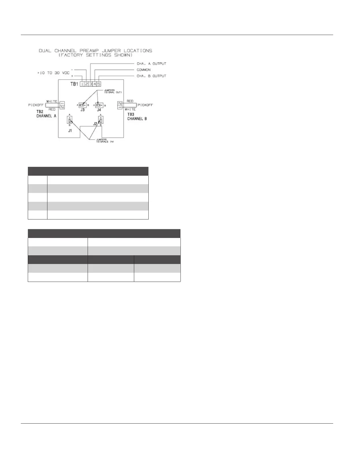
TB1 Function
1 9-28 VDC Supply
2 V Comm
3 Channel A Signal
4 Channel A and B Common
5 Channel B Signal
Jumper Position
J1 (Channel A) B
1
J2 (Channel B) B
1
5 VDC Pulse V Supply Pulse
2
J3 (Channel A) A B
J4 (Channel B) A B
Figure 8-1 Wiring Connections
NOTE:
1
Do not Change without consulting factory.
2
V Supply Pulse = Input V minus approximately 2 volts
The instrument should not be located in a location
where excessive vibration is to be expected.
Care should be taken not to locate the instrument
near any source of electromagnetic interference, such
as those produced by electric motors, transformers,
solenoids, etc.
Either of these factors could induce a signal into the
flow sensing pickoff and interfere with the accuracy of
line product measurement.
 Loading...