Page 22/58IOM BiRotor Plus R27
9.1 - Removal/Replacement of Circuit Board
1. Disconnect all power to the instrument.
2. Remove the electronics cover, or electronics
register, if one is fitted, by removing four Allen
screws.
3. Disconnect terminals and wiring to the circuit
board.
4. Remove circuit board by removing the screws
that attach it to the housing.
To reinstall, reverse the removal instructions and
torque the four Allen screws to 55 in/lbs.
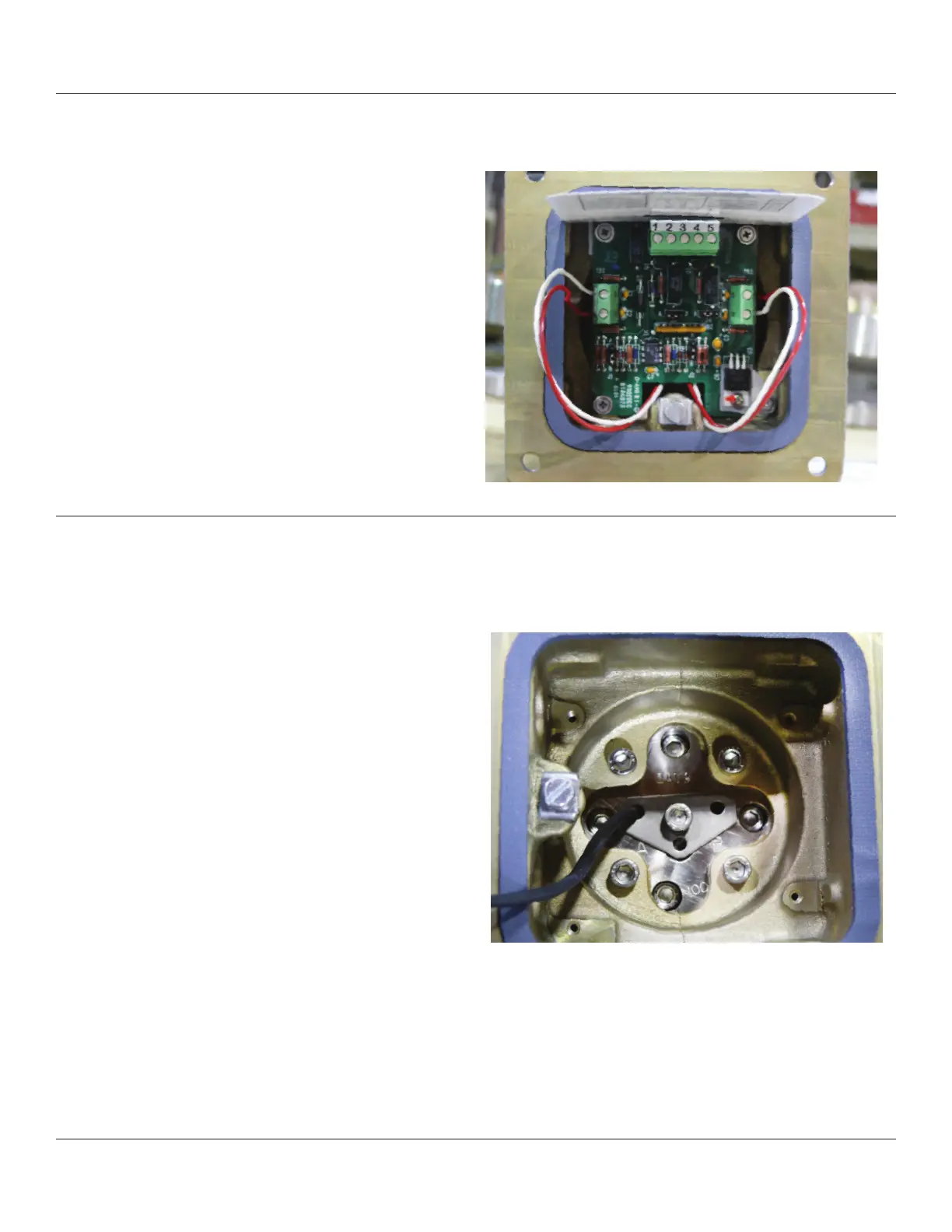
Figure 9-1 Circuit Board and Housing
9.2 - Removal/Replacement of Pick Off Sensors
1. Remove the circuit board as detailed above.
2. Remove the center screw from the sensor
housing and lift off the hold down washer.
3. Lift out the inductive sensor(s) and spring.
Resistance between sensor leads:
For Sensor P/N 899-00-201-00 or P/N 899-00-201-01:
1000 Ohms +/-15%
For Sensor P/N 899-00-201-00-B or
P/N 899-00-201-01-B: 750 Ohms +/-15%
Resistance between leads and housing when
installed: 10 M Ohms
If any of this is not the case the pick off should be
replaced.
To reassemble, replace the pick off sensor
in the sensor housing. If only one pick off sensor is
present it should be inserted in the hole labeled ‘A’.
Secure with the hold down washer and Allen screws
and replace the circuit board (Item 38).
Figure 9-2 Pick Off Sensor Installation