Page 18/58IOM BiRotor Plus R27
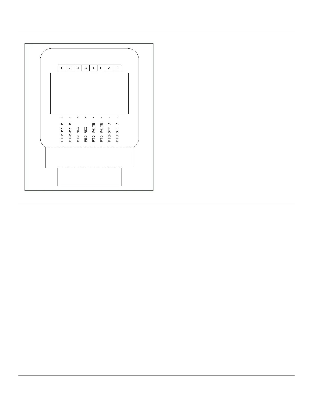
Figure 8-2 Wiring Connections
Integral Brodie Electronic Rate Totalizer
(BERT-E)
If the instrument has been supplied with an
integral electronic register, the internal wiring
connections will already be in place. For additional
functions and wiring possibilities please refer to
the BERT-E’s instruction manual.
8.3 - Meter Start Up and Operation
Review the system installation to ensure all the
components are in proper sequence, all isolation
valves must be closed, all electrical connections
are complete, and all covers are in place.
1. To pressurize the system, slowly open the
inlet valve so as to prevent system shock.
Slowly allow product to enter the system while
keeping the downstream isolation valve closed.
2. Open the downstream valve (10%) to allow
any air to be flushed from the system. Do not
overspeed the instrument.
3. Once the air has been flushed from the system,
close the downstream isolation valve and check
for any leaks. If leaks are found, check all seals
and retighten connections.
4. Fully open the upstream isolation valve to
pressurize the system.
Flow start up can commence once the system has
been pressurized.
1. Turn on all electronic circuits and check for
proper function.
2. Open flow control valves and allow the
instrument to run at 20% of its rated flow for 5
minutes.
3. During this initial run, check all other
components in the system for functionality.
4. Once this run is complete, set the flow control
valve to the required flow and ensure that
the maximum flow for the instrument is not
exceeded.