IOM BiRotor Plus R27Page 27/58
9.7 - Complete Reassembly (B27 thru B34)
1. Ensure all parts are clean and free of debris.
2. Lubricate all bearings and internal O-rings with
a light oil.
NOTE:
All O-rings should be replaced with new ones
during reassembly.
3. Press bearings into the end plates. Use a hand
press and ensure that the bearing is pressed
on the outer race to avoid damage. The bearing
races should be flush with the bottom of the
end plate once the bearings have been pressed
in correctly. The outer race of an old bearing
can be used to assist in proper seating.
4. Attach one end plate to the measuring unit
body at the end opposite the O-ring grove
in the measuring unit body. Align the dowel
pins and gently tap into place with a plastic or
rubber mallet. Once fully seated secure the end
plate with screws.
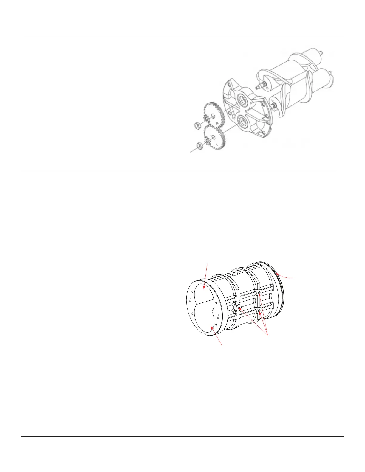
5. Each rotor and timing gear is marked with an
‘R’ or an ‘L’. During assembly the inscriptions
need to be matched. To orientate the rotors
during assembly the measuring element
body has three holes machined into it for
manufacturing purposes. These holes should be
positioned so that they face upwards. With these
holes facing upwards turn the housing so that
the end with O-ring groove is closest to you. With
the housing in this position the rotor marked with
an ‘R’ goes in the right hand cavity and the rotor
marked with an ‘L’ goes in the left hand cavity.
12. The bearings can be removed from the end
plates by pressing on the inner race of the
bearings from the outside of the plate. If the
bearings are removed from the endplates, then
they must be replaced. Timing gears must be
replaced whenever bearings are replaced.
13. Remove the other end plate from the
measuring element housing and remove the
bearings.
14. Remove the sensor housing from the inlet
housing by removing found Allen screws
located in the counter sunk holes under the
circuit board.
Figure 9-4 Rotor and Gear Orientation
Figure 9-5 Measuring element body
Machined Holes
Right hand rotor in this bore
Left hand rotor in this bore
O-ring groove