BRONKHORST®
Page7FlowDDE 9.17.067
2.2 RS232ONMULTIBUSINSTRUMENT
TheRS232interfaceonamultibusinstrumentcanbeconnectedtoanyRS232V24serial(computer)port.Makesure
torespectthehook‐updiagram.Bronkhorst®offersspecialcablesforcommunication,separatingtheRS232linesfrom
thepowerandanalogin‐andoutput.Onthe9‐pinmaleD‐subconnectoroftheinstrumentRXandTXareavailableon
pin6andpin1.
Serial RS232 communication on a multibus instrument with RS232 can be treated as a FLOW‐BUS system with one
instrumentandaFLOW‐BUS/RS232interface.IncaseaFLOW‐BUS fieldbus connectionispresent,other
instruments
connectedtotheFLOW‐BUScanbecommunicatedwithaswell.
RS232communicationispossibleby:
9‐pinSubD‐connector (non‐IP65instruments,e.g.EL‐FLOW)
8‐pinDINconnector (IP65instruments,e.g.CORI‐FLOW)
Fortheexactconnectionspleaseadviseyourhook‐updiagram.
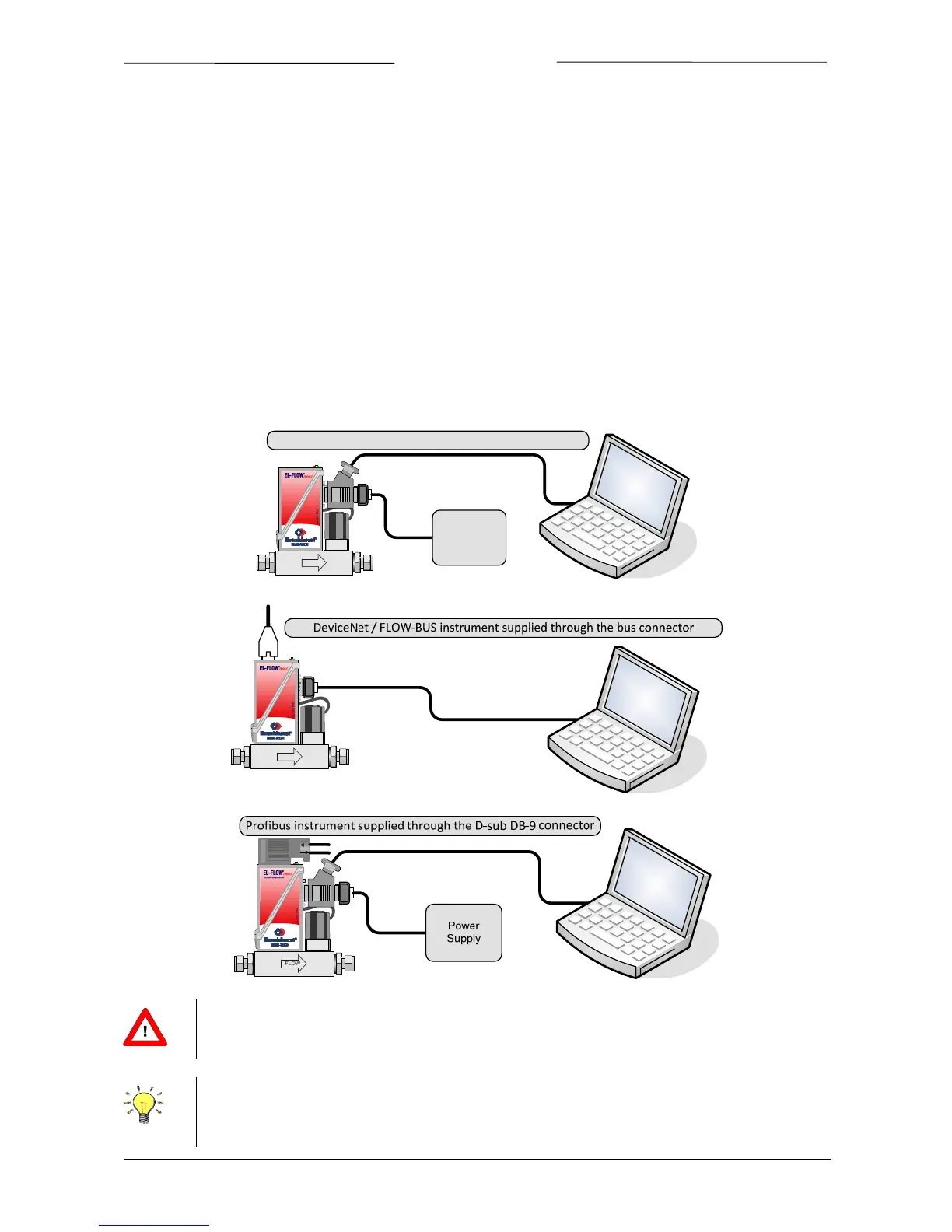
2.2.1 Applications,e.g.EL‐FLOW
FLOW
mass flow meter/controller
Power
Supply
InstrumentsuppliedthroughtheD‐subDB‐9connector
FLOW
mass flow meter/controller
Forpropercableinstallationpleaseconsulttheapplicablehook‐updiagrammentionedinparagraph
1.2.2
Bydefault,theinterfaceofferscommunicationatabaudrateof38400baud.Oninstrumentsthatoffer
thepossibilitytochangetheRS232baudrate,thebaudratemaybeconfigureddifferently.Seethe
technicaldocumentationofyourinstrumentwhichbaudratesaresupported.