Do you have a question about the Broseley eVolution and is the answer not in the manual?
Lists all components included with the burner and stove boxes.
Specifies the appliance is designed for Natural Gas G20.
Details the required inlet pressure for the appliance.
Specifies the type of pipe for gas connection.
Indicates the maximum heat input rate of the appliance.
Indicates the minimum heat input rate of the appliance.
Specifies the maximum wall thickness the appliance can accommodate.
Defines the minimum required length of the flue pipe.
Classifies the appliance based on Nitrogen Oxide emissions.
Classifies the appliance based on its energy efficiency.
Details required distances for flue terminal placement relative to openings and building features.
Explains when a terminal guard is required for safety.
Specifies the maximum allowable flue length for the installation.
Defines the minimum flue length required for proper operation.
Details minimum clearances required around the appliance.
Specifies the minimum thickness of the hearth.
Details required clearances around the appliance, including hearth protrusion.
Notes on curtains and use of an additional guard for child safety.
Guidance on preparing the gas supply for connection.
Instructions for removing the transit bracket and burner bracket.
Details on aligning and securing the burner bracket to the burner assembly.
Guidance on adjusting the burner bracket arms for installation.
Using a template to mark the flue position for drilling.
Instructions for drilling and plugging holes for bracket arms.
Steps to secure the flue pipe to the burner assembly.
Emphasizes creating an airtight seal between the spigot and flue pipe.
How to secure the wall plate and seal it to the brickwork.
Final step to ensure burner bracket arms are securely fixed.
Instructions for assembling and fitting the terminal guard to the external wall.
Details on connecting the gas supply pipe using 8mm copper tubing.
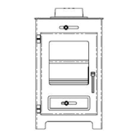
Instructions for removing the front glass frame assembly.
Warning to handle the ceramics with care during unpacking.
Guidance on positioning the main fuel bed ceramic.
Instructions for positioning the front right ceramic piece.
Instructions for positioning the front left ceramic piece.
Guidance on positioning the rear right ceramic piece.
Instructions for positioning the rear left ceramic piece.
Emphasizes using only original manufacturer's ceramics.
Instructions for refitting the glass panel assembly after ceramics are placed.
How to attach the top cover plate using the provided magnets.
Instructions for attaching the main stove body to the burner bracket.
How to position the steel fret and blanking disc.
Procedure for testing the appliance's operating pressure.
Detailed steps for lighting the pilot light.
Notes that a strong odour during initial firing is normal.
Step-by-step guide to lighting the pilot and main burner.
Instructions for adjusting the appliance's heat output settings.
How to set the appliance to operate on pilot flame only.
Procedure for safely turning off the appliance.
Safety measures when handling refractory ceramic fibres (RCF).
General instructions for cleaning the appliance's metal parts.
Guidance on handling and cleaning the fragile fuel bed ceramics.
Details on removing the burner tray for servicing gas components.
Step-by-step guide to removing gas carrying components.
Procedure for removing and replacing the pilot assembly.
Instructions for removing and replacing the injector.
| Category | Wood Stove |
|---|---|
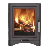
| Brand | Broseley |
| Fuel Type | Wood |
| Heat Output | 5kW |
| Flue Size | 125mm |